Backlight assembly for liquid crystal display device and liquid crystal display device using the same

Active Publication Date: 2006-12-14
LG DISPLAY CO LTD
View PDF18 Cites 64 Cited by
  • Summary
  • Abstract
  • Description
  • Claims
  • Application Information

AI Technical Summary

Benefits of technology

[0015] Another object of the present invention is to provide a backlight assembly for a liquid crystal display device and a liquid crystal display device using the same for increasing contrast.
[00

Problems solved by technology

The LCD device according to the related art has problems.
Thus, an LCD device acco

Method used


Image

  • Backlight assembly for liquid crystal display device and liquid crystal display device using the same
  • Backlight assembly for liquid crystal display device and liquid crystal display device using the same
  • Backlight assembly for liquid crystal display device and liquid crystal display device using the same

Examples


Example

[0035] Reference will now be made in detail to the preferred embodiments, examples of which are illustrated in the accompanying drawings.

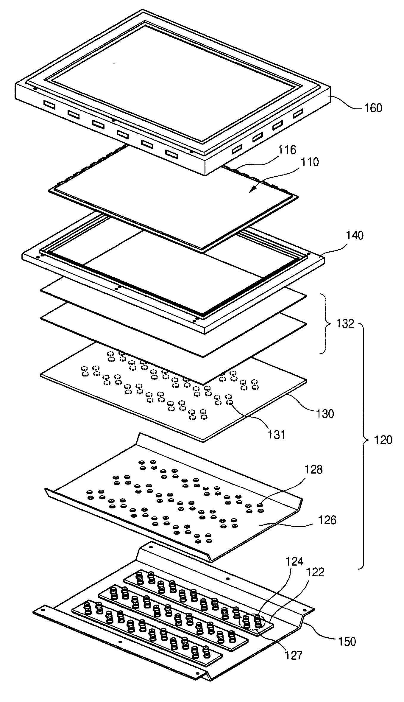
[0036]FIG. 5 is an exploded perspective view of an LCD device using LEDs as a light source in a backlight according to a first exemplary embodiment of the present invention. As shown in FIG. 5, the LCD device includes a liquid crystal panel 110, a backlight assembly 120, a main frame 140, a bottom frame 150 and a top frame 160. The liquid crystal panel 110 includes first and second substrates facing each other (not shown), a liquid crystal layer (not shown) interposed between the first and second substrates, and a PCB 116 adjacent to the edge of the liquid crystal panel 110. The main frame 140 surrounds the sides of the liquid crystal panel 110 and the backlight assembly 120. The bottom frame 150 covers a rear surface of the backlight assembly 120 and can be attached to the main frame 140. The top frame 160 surrounds an edge of the liquid crystal ...


PUM


Abstract

A backlight assembly for a liquid crystal display device includes a bottom frame having an inner surface, printed circuit boards on the inner surface, and a plurality of light emitting diodes in rectangular-shaped clusters on each of the printed circuit boards, each of the light emitting diode clusters includes four light emitting diodes.

Description

[0001] The present application claims the benefit of Korean Patent Application No. Korean Patent Application No. P2005-046273 filed in Korea on May 31, 2005 and P2005-0109218 filed in Korea on Nov. 15, 2005, which are both hereby incorporated by reference in their entirety. BACKGROUND OF THE INVENTION [0002] 1. Field of the Invention [0003] The present invention relates to a backlight assembly, and more particularly, to a backlight assembly for a liquid crystal display device and a liquid crystal display device using the same. Although the present invention is suitable for a wide scope of applications, it is particularly suitable for an arrangement in which light emitting diodes (LEDs) are used as light sources in a backlight assembly. [0004] 2. Discussion of the Related Art [0005] In general, a display device portrays information as visual images. As communication technology has developed, a need for compact display devices has developed. Such display device can be classified as ei...

Claims


Application Information

Patent Timeline
IPC IPC(8): G02F1/1335F21V29/00H01L33/60
CPCG02F1/133603G02F2001/133613G02F1/133611G02F1/133605G02F1/133613Y10S362/80G09G3/3406
Inventor HAN, GIL-WONHONG, HEE-JUNGLIM, MOO-JONGBANG, JU-YOUNGCHOI, JONG-HYUN
Owner LG DISPLAY CO LTD
Why Eureka
Try Eureka