Video analysis system of swing motion

a video analysis and swing motion technology, applied in the field of video analysis systems of swing motion, can solve the problems of difficult operation of video, inability to identify the swing motion from a recording medium and display the and inability to draw lines, etc., and achieve the effect of easy determination and display of video of the swing motion

Inactive Publication Date: 2006-12-14
BRIDGESTONE SPORTS
View PDF23 Cites 28 Cited by
  • Summary
  • Abstract
  • Description
  • Claims
  • Application Information

AI Technical Summary

Benefits of technology

[0020] According to this configuration, since the control unit has the functions (a) to (h), the video of the swing motion of hitting a ball can be analyzed without using a personal computer. Also, if necessary or an operator has advanced capability, advanced swing analysis may be conducted using a personal computer. Further, the control unit may identify the impact time based on the impact detection signal received from the impact detection unit and records the video of the swing motion for the predetermined time period containing the impact time. Therefore, the video of swing motion can be easily determined and displayed.

Problems solved by technology

However, generally the swing motion can be recorded only from one direction with the general-purpose video camera, and it is troublesome to identify the swing motion from a recording medium and display the video of the swing motion.
However, a line, etc., cannot be drawn on the monitor screen and it is not easy to operate the video.
However, no apparatus or technique for enabling students to easily compare the two video images has been proposed.
Therefore, there arises a problem that users are required to have a preliminary knowledge about basic software such as Windows (registered trademark), etc., to operate those systems.

Method used


Image

  • Video analysis system of swing motion
  • Video analysis system of swing motion
  • Video analysis system of swing motion

Examples


Embodiment Construction

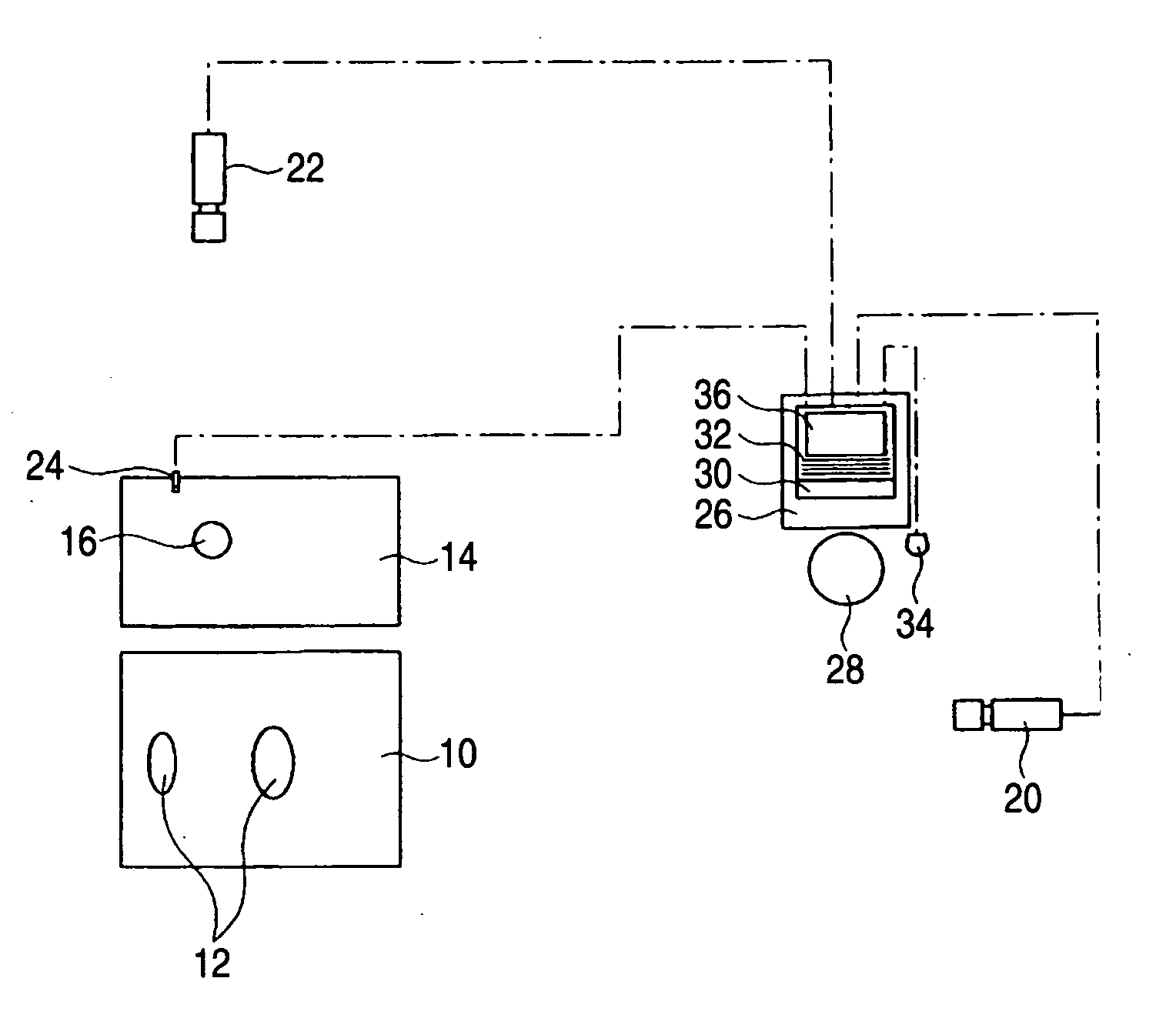
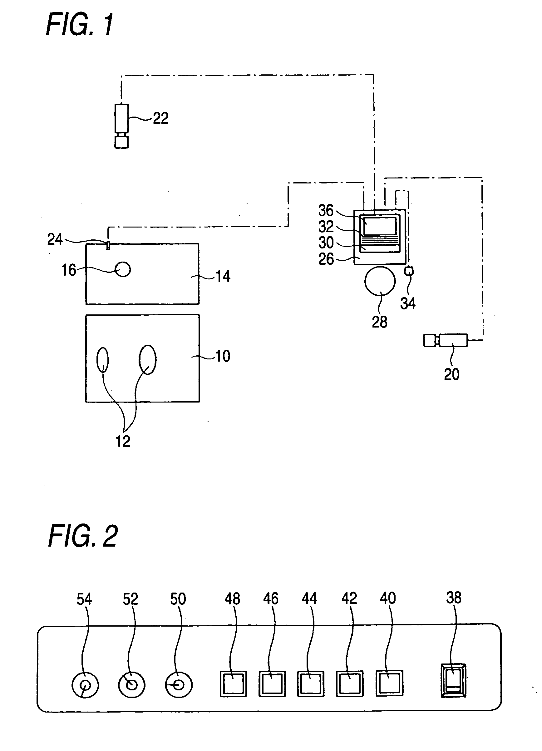
[0031] Although embodiments of the invention will be described with reference to the accompanying drawings, the invention is not limited to the following examples. FIG. 1 is a plan view to show an example of a video analysis system of swing motion according to an embodiment of the invention. In FIG. 1, numeral 10 denotes a stance mat on which a golfer who hits a golf ball stands. Numeral 12 denotes a stance position. Numeral 14 denotes a shot mat where a ball is set. Numeral 16 denotes a tee position.

[0032] In FIG. 1, numeral 20 denotes a first camera for imaging a golfer from the rear. Numeral 22 denotes a second camera for imaging a golfer from the front. In this system, the first camera 20 and the second camera 22 function as an imaging unit that images video of swing motion. The first camera 20 and the second camera 22 are shutter-type CCD cameras and are set to appropriate heights with tripods.

[0033] In FIG. 1, numeral 24 denotes a pin-type sensor microphone (hereinafter simp...


PUM


Abstract

A video analysis system of swing motion includes an imaging unit that images video of swing motion, an impact detection unit that detects impact, a control unit and a video display unit. The control unit has (a) a function of receiving the video of the swing motion from the imaging unit; (b) a function of receiving an impact detection signal from the impact detection unit; (c) a function of recording the video of swing motion received from the imaging unit into the control unit; and (d) a function of, when the control unit records into the control unit the video of the swing motion received from the imaging unit, determining an impact time based on the impact detection signal received from the impact detection unit, to record images of the swing motion for a predetermined time period containing the impact time.

Description

CROSS-REFERENCE TO RELATED APPLICATION [0001] This application is based upon and claims the benefit of priority from the Japanese Patent Application No.2005-86004 filed on Mar. 24, 2005; the entire contents of which are incorporated herein by reference. BACKGROUND OF THE INVENTION [0002] 1. Field of the Invention [0003] This invention relates to a video analysis system of swing motion in sports of hitting a ball, such as golf and baseball. [0004] 2. Description of the Related Art [0005] Hitherto, in golf, for a golfer to improve his or her swing motion for improving the golf skill, generally the golfer has consulted a golf teacher called an instructor about his / her swing motion and has gotten an instructor's advice on the swing motion; it has been a common practice for the golfer to take such lessens in a golf school. In the golf school, it is also a common practice that the swing of a student golfer is recorded with a general-purpose video camera and that the student golfer watches...

Claims


Application Information

Patent Timeline
Patent Type & Authority Applications(United States)
IPC IPC(8): A63B69/00
CPCA63B24/0003A63B24/0021A63B69/36A63B69/3658G06K9/00342A63B2069/0008A63B2220/62A63B2220/806A63B2220/808A63B2024/0031G06V40/23
Inventor KATAYAMA, HIDE
Owner BRIDGESTONE SPORTS
Why Eureka
Try Eureka