Trajectory stability increased golf clubs with pluralities of holes

a golf club and plurality technology, applied in the field of golf club heads, can solve the problems of slight shake of the drag force, and achieve the effects of stabilizing the trajectory, and increasing the stability of the swing trajectory

Inactive Publication Date: 2006-12-14
KIM YEOUNG HO +1
View PDF10 Cites 10 Cited by
  • Summary
  • Abstract
  • Description
  • Claims
  • Application Information

AI Technical Summary

Benefits of technology

[0009] It is an object of the present invention to provide a golf club head having increased stability of its swing trajectory. The golf club driver head of the current application, with increased trajectory stability, has a number of holes developed on the head by installing a number of metal tubes of 3 mm diameter between the front face and rear face of the head. The holes developed on the club head allow air pass through and the air stream stabilizes the trajectory of the club head's swing. This stabilized swing trajectory increases the possibility of a golf ball hit at the right point and stay on the green of the golf course. Other golf clubs, irons, also have pluralities of holes on the head developed by punching holes with drills. When a player swings a driver for T-off, the speed of a driver club head reaches well over 40˜50 meter / second. This speed is over 150 kmn / hr. At this speed, the resistance of air to the club head is significant. Even a slight unbalance of the drag force shakes the trajectory of the club head and moves the hitting point of the golf club from the center of the club head. Irons are usually used on the fair way of a golf course for medium range hitting. High-speed swing is not necessary in such situation. However, some player T-off with an iron. In that case, the player needs an iron with stable swing trajectory. It is the purpose of the current application to provide a golf club head, including a driver's head, which increases the stability of the trajectory of the club head to increase the accuracy of the impact, especially at T-off moment.

Problems solved by technology

Even a slight unbalance of the drag force shakes the trajectory of the club head and moves the hitting point of the golf club from the center of the club head.

Method used


Image

  • Trajectory stability increased golf clubs with pluralities of holes
  • Trajectory stability increased golf clubs with pluralities of holes
  • Trajectory stability increased golf clubs with pluralities of holes

Examples


Embodiment Construction

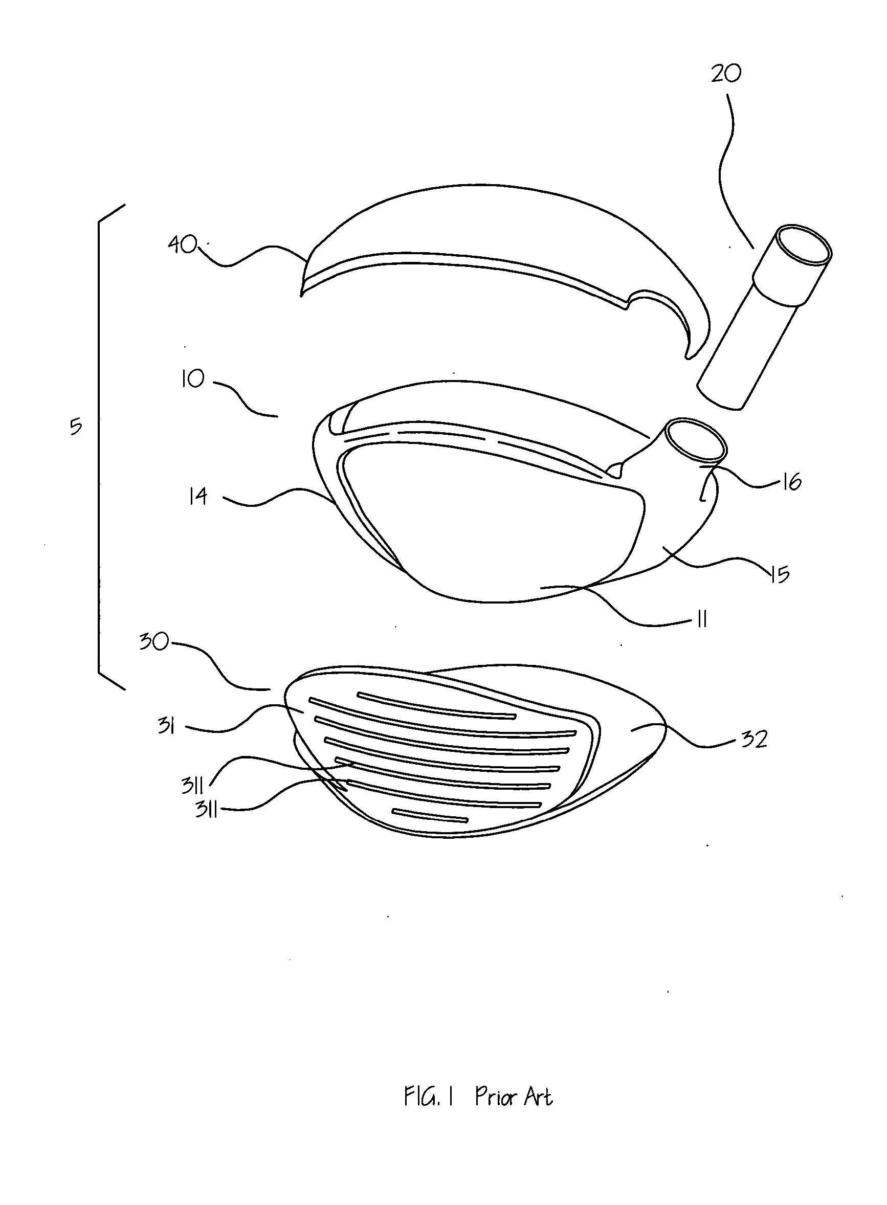
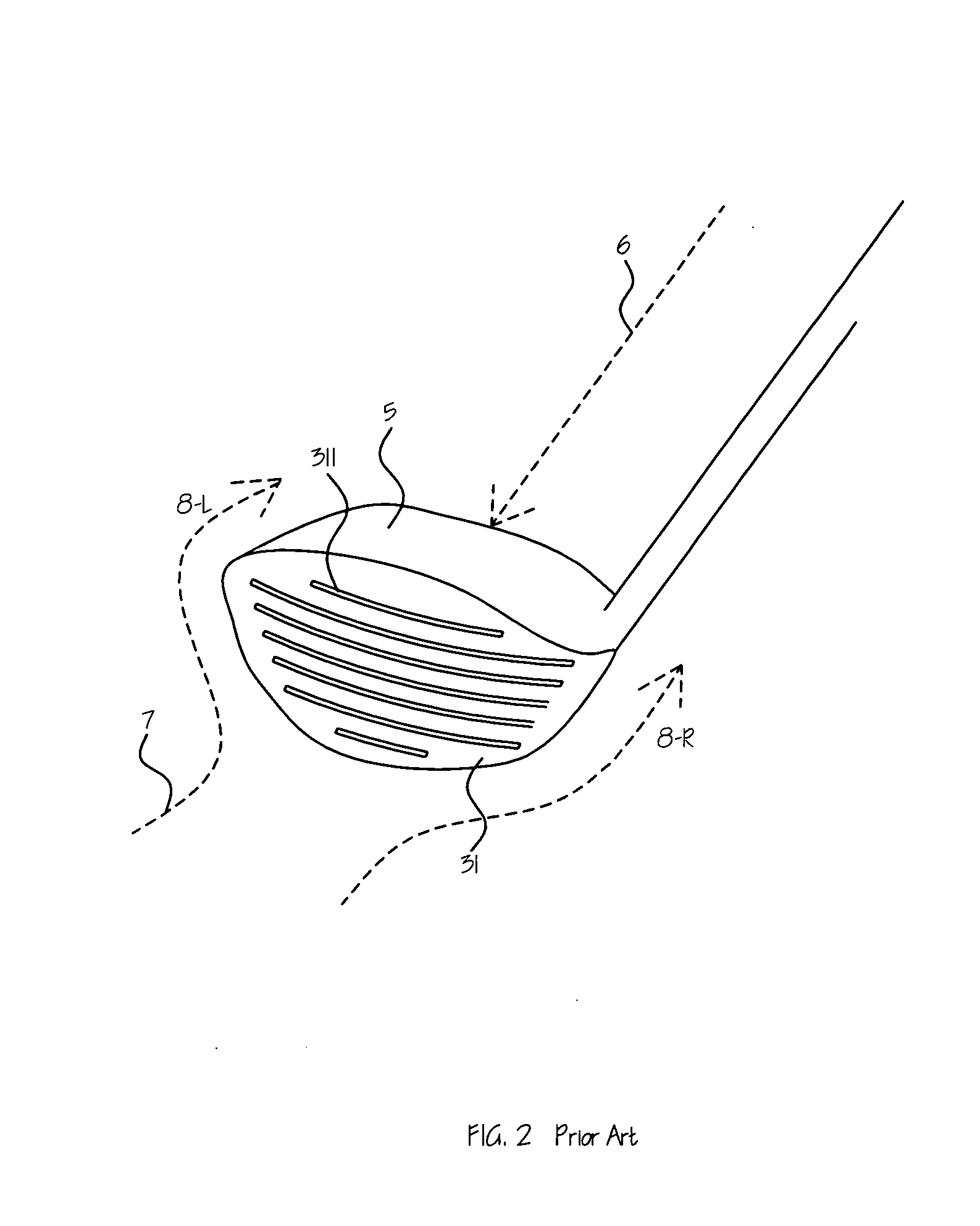
[0020]FIG. 1 is an exploded view of a golf driver club head 5 of the prior art. The golf club head 5 is shown comprised of a casing 10, an axle tube 20, a packing plate 30, and a cover plate 40. The casing 10 is made of a compound material subject to a predetermined shape. The casing 10 has a front face 11, a bottom face 12, a back face 13, a toe 14, a heel 15, and a neck 16. The inside of the casing 10 is hollow. The topside of the casing 10 is opened. The axle tube 20 is a stepped metal tube fitted into the neck 16 of the casing 10 for receiving a club shaft (not shown). The packing plate 30 is a substantially L-shaped thin sheet of metals fixedly fastened to the front face 11 and bottom face 12 of the casing 10, forming the face panel 31 and sole 32 of the golf club head 5. The face panel 31 has a plurality of hitting grooves 311 thereon. The primary role of these hitting grooves is to increase a contact area. The second role of these hitting grooves is to distribute air to both ...


PUM


Abstract

A golf club head is provided, which has a number of holes developed on the head by installing a number of metal tubes of 3 mm diameter between the front face and rear face of the head. Another embodiment of the current application is a golf iron having a number of holes on the head. Air stream through the holes stabilizes the trajectory of the golf clubs at high speed of swing.

Description

BACKGROUND OF THE INVENTION [0001] Driving is known as the most important and frustrating part of golf game. If a golf ball is not hit at right angle and with the proper strength, the ball flies to a wrong direction and falls in a rough. However, most of golf drivers are designed to maximize a flying distance of a golf ball and focused on maximizing repulsion force. None of them concerns about a stability of the trajectory of a driver when a player does swing. When a player swings a driver for T-off, the speed of a driver club head reaches well over 40˜50 meter / second. This speed is over 150 km / hr. At this speed, the resistance of air to the club head is significant. Even a slight unbalance of the drag force shakes the trajectory of the club head and moves the hitting point of the golf club from the center of the club head. It is the purpose of the current application to provide a golf club head, including a driver's head, which increases the stability of the trajectory of the club ...

Claims


Application Information

Patent Timeline
Patent Type & Authority Applications(United States)
IPC IPC(8): A63B53/00
CPCA63B53/04A63B53/0475A63B59/0088A63B53/047A63B2209/00A63B2225/01A63B53/0466A63B2053/0416A63B60/50A63B53/0416A63B60/006A47K7/04A63B60/00
Inventor KIM, YEOUNG HOKIM, MAXWELL S.
Owner KIM YEOUNG HO
Why Eureka
Try Eureka