Water circulation apparatus

Inactive Publication Date: 2006-12-21
VANDECAMP HEATING
View PDF8 Cites 11 Cited by
  • Summary
  • Abstract
  • Description
  • Claims
  • Application Information

AI Technical Summary

Benefits of technology

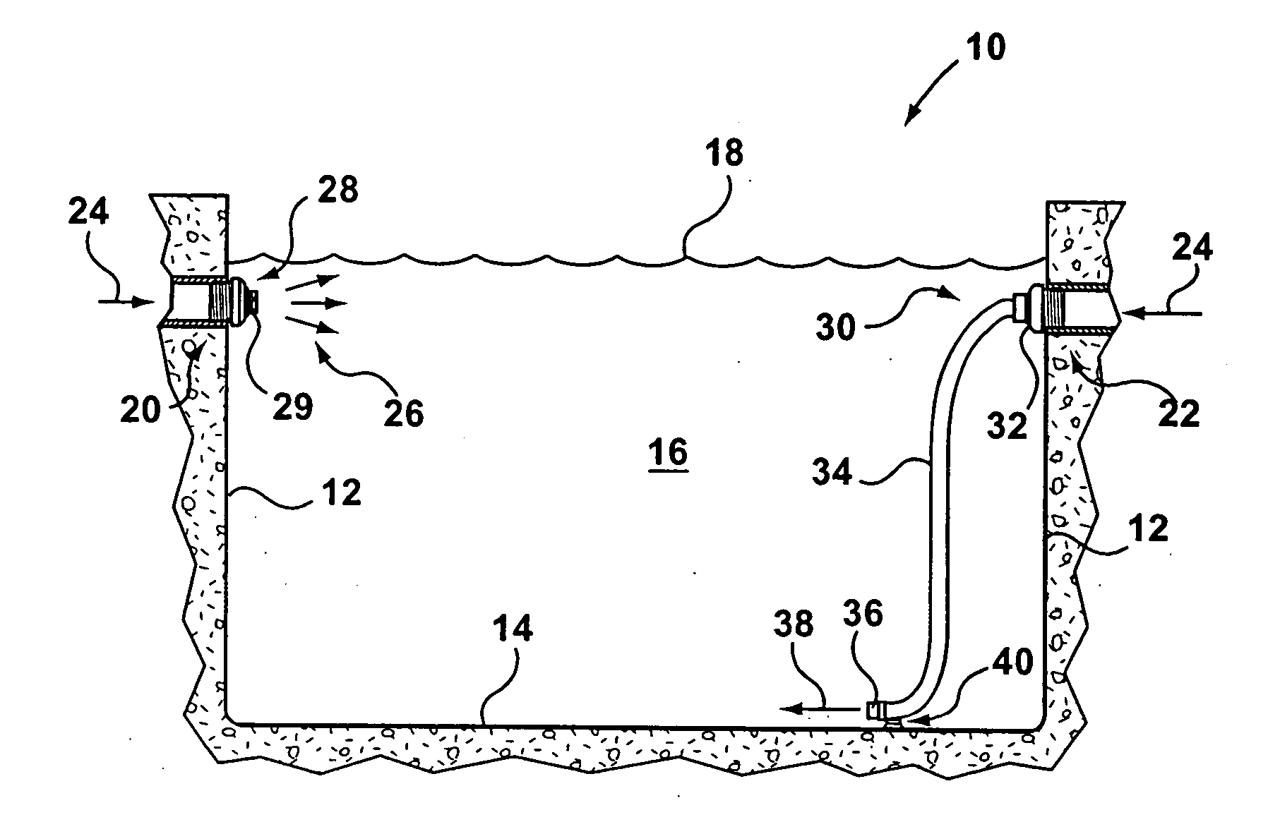
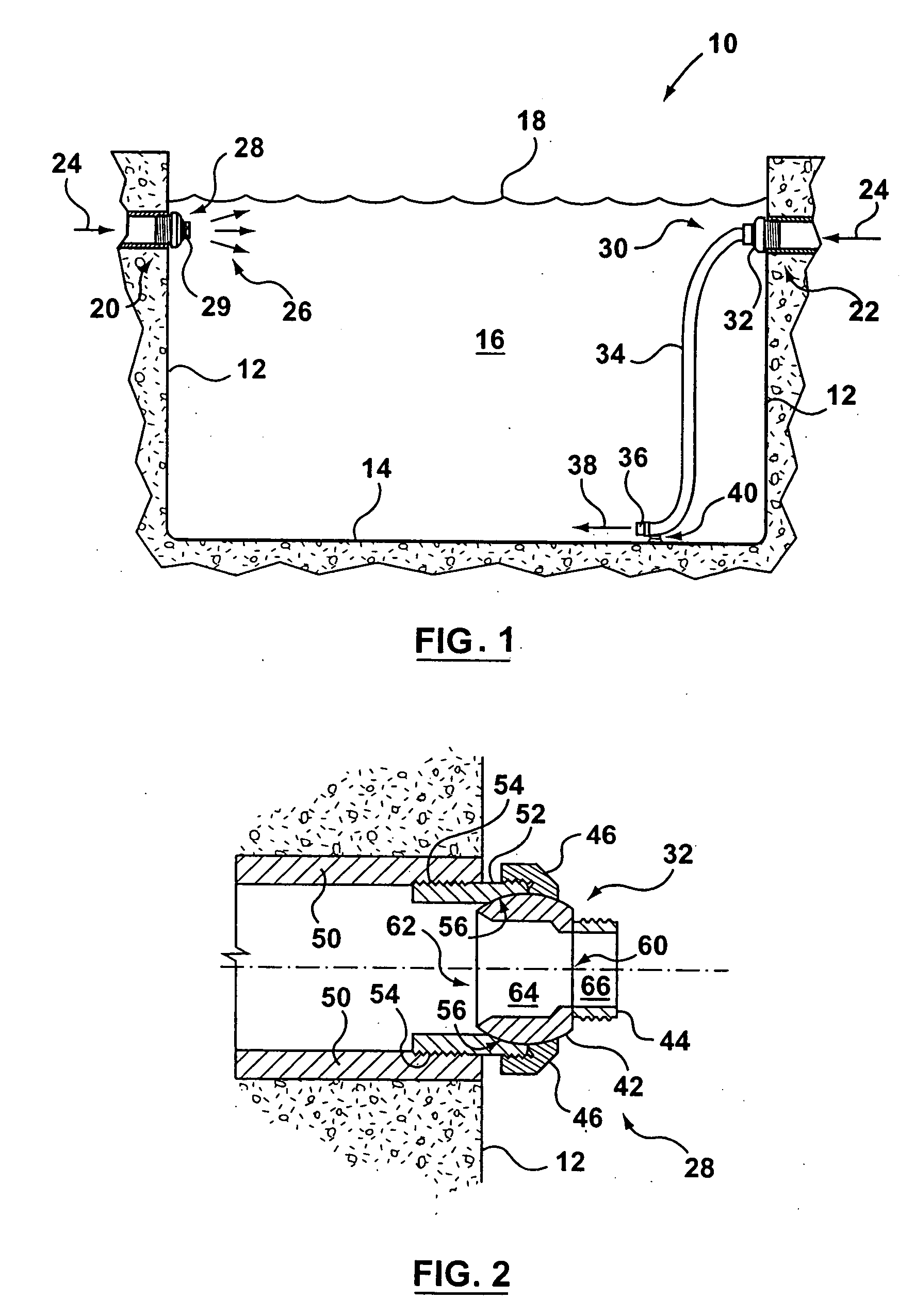
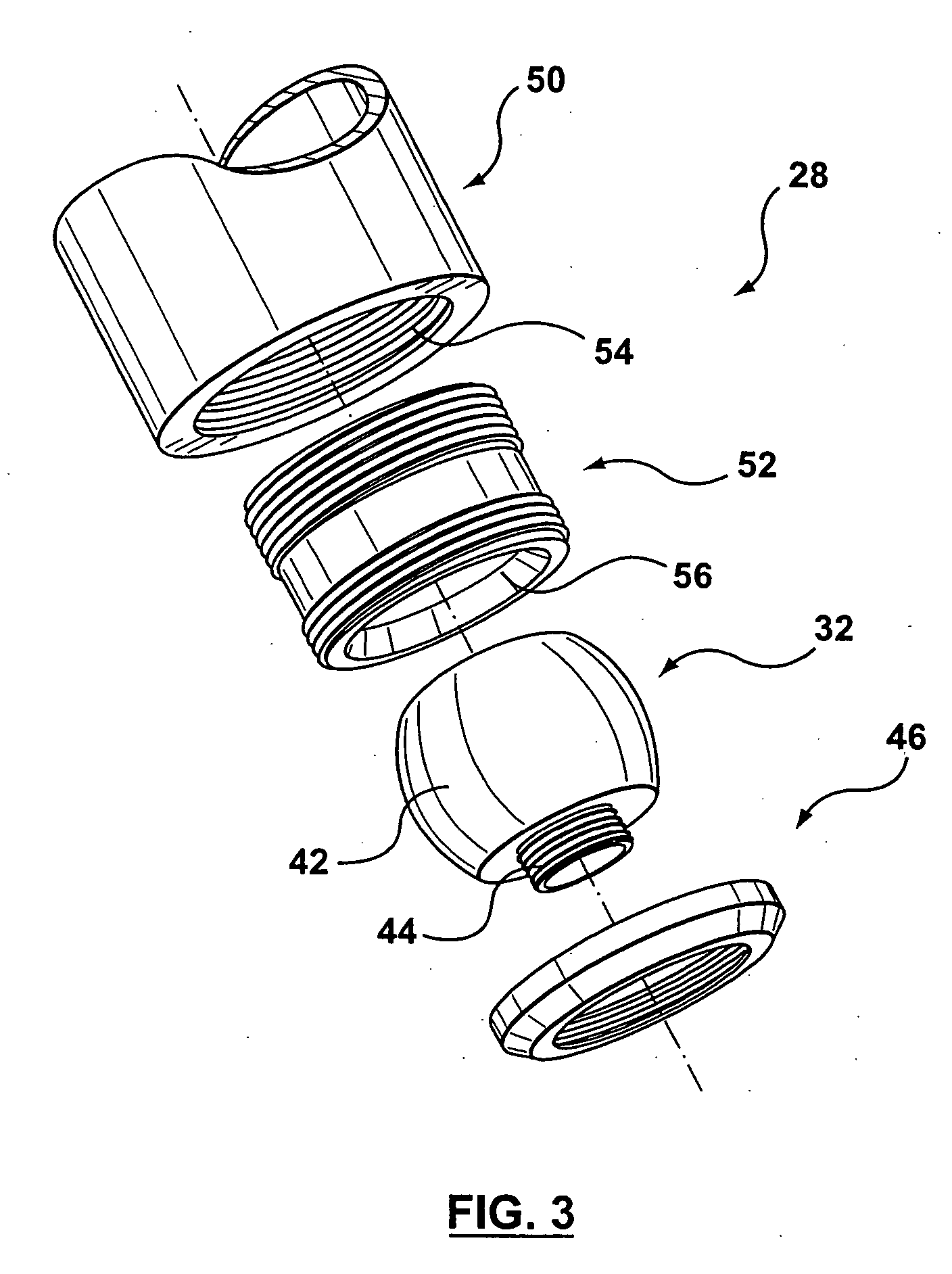
[0005] The present invention provides a water circulation apparatus for a swimming pool or hot tub. The water circulation apparatus includes an eyeball connector and an extension hose. The eyeball connector includes a spherical eyeball and a first connector. The extension hose includes a second connector for coupling to the first connector. The eyeball connector fits within a water ret

Problems solved by technology

This results in an undesirable temperature gradient from the bottom of the pool to the top.
Accordingly, the energy expended in heating the water that is returned to the pool may be quickly lost.

Method used


Image

  • Water circulation apparatus
  • Water circulation apparatus
  • Water circulation apparatus

Examples


first embodiment

[0030] In a first embodiment, shown in FIG. 4, first connector 44 includes a threaded exterior surface 68. The extension hose 34 includes a second connector 70 having an interior threaded surface adapted to matingly engage the threaded exterior surface 68 of the first connector 44, thereby connecting the extension hose 34 to the eyeball connector 32. In one embodiment, the first connector 44 and the second connector 70 have the diameters and threading of standard ½ inch or ¾ inch garden hose connectors. The second connector 70 may include a rubber washer 72 to improve the seal between the first connector 44 and the second connector 70. In this embodiment, first connector 44 may have sufficient axial length that it can be screwed deeply enough into second connector 70 so that rubber washer 72 is engaged.

second embodiment

[0031] In a second embodiment, illustrated in FIG. 5, first connector 44 features a ridged exterior surface 74 and is intended for insertion directly into the extension hose 34. In this embodiment, the second connector includes a hose clip 76 encircling the extension hose 34. The hose clip 76 serves to bind the extension hose 34 to the first connector 44. The ridged exterior surface 74 provides resistance to prevent the extension hose 34 from pulling away from the eyeball connector 32.

third embodiment

[0032] In a third embodiment, shown in FIG. 6, the first connector 44 and the second connector 70 include the respective halves of a snap-fit or push-fit connector. The snap-fit connector may, for example, be compatible with the snap-fit garden hose connectors marketed in Canada under the brand GARDENA by Gardena Canada Ltd. of Brampton, Ontario.

[0033] Those of ordinary skill in the art will appreciate that the first connector 44 and second connector 70 may include a wide range of embodiments provided the respective connectors 44 and 70 facilitate fluid communication and secure the extension hose 34 to the spherical eyeball 42. Those of ordinary skill in the art will further appreciate that the first connector 44 may be attached to the spherical eyeball 42 to form the eyeball connector 32 in some embodiments. The attachment of the first connector 44 to the spherical eyeball 42 may, for example, include adhesive bonding, heat welding, and / or other methods of attachment. In other embo...


PUM


Abstract

A water circulation apparatus for a swimming pool or hot tub. The water circulation apparatus includes an eyeball connector and an extension hose. The eyeball connector includes a spherical eyeball and a first connector. The extension hose includes a second connector for coupling to the first connector. The eyeball connector fits within a water return line housing in the sidewall of the swimming pool or hot tub. Heated water returned to the pool through the water return line is routed through the eyeball connector into the extension house and is expelled in the pool through the free end of the extension hose. The extension hose may include a weighted free end to ensure that the heated return water is expelled at the bottom of the pool. The weighted free end may include a diffuser.

Description

FIELD OF THE INVENTION [0001] This invention relates to a water circulation apparatus for use with a swimming pool water return line, which can be used to direct water flow, through a tube, toward the bottom of the swimming pool. BACKGROUND [0002] Swimming pools, hot tubs, and the like provide for water circulation by drawing water from the pool, heating the water, and pumping the heated water back into the pool through a return outlet. The water return outlet is typically mounted on the wall of the pool or tub. A typical water return outlet includes an eyeball assembly. The eyeball assembly provides for a limited range of rotational motion. This allows for the jet of returning water to be pointed in a selected direction. [0003] The eyeball assemblies are typically mounted near the surface of the water in the swimming pool or tub. When heated water is expelled through the eyeball assembly into the upper portion of the swimming pool, the heated water tends to remain at the surface an...

Claims


Application Information

Patent Timeline
IPC IPC(8): E04H4/00
CPCE04H4/129E04H4/12
Inventor VANDECAMP, BILL
Owner VANDECAMP HEATING
Why Eureka
Try Eureka