

Passive and wireless acoustic wave accelerometer
- Summary
- Abstract
- Description
- Claims
- Application Information
AI Technical Summary
Benefits of technology
Problems solved by technology
Method used
Image

Examples
Embodiment Construction
[0021] The particular values and configurations discussed in these non-limiting examples can be varied and are cited merely to illustrate at least one embodiment and are not intended to limit the scope thereof.
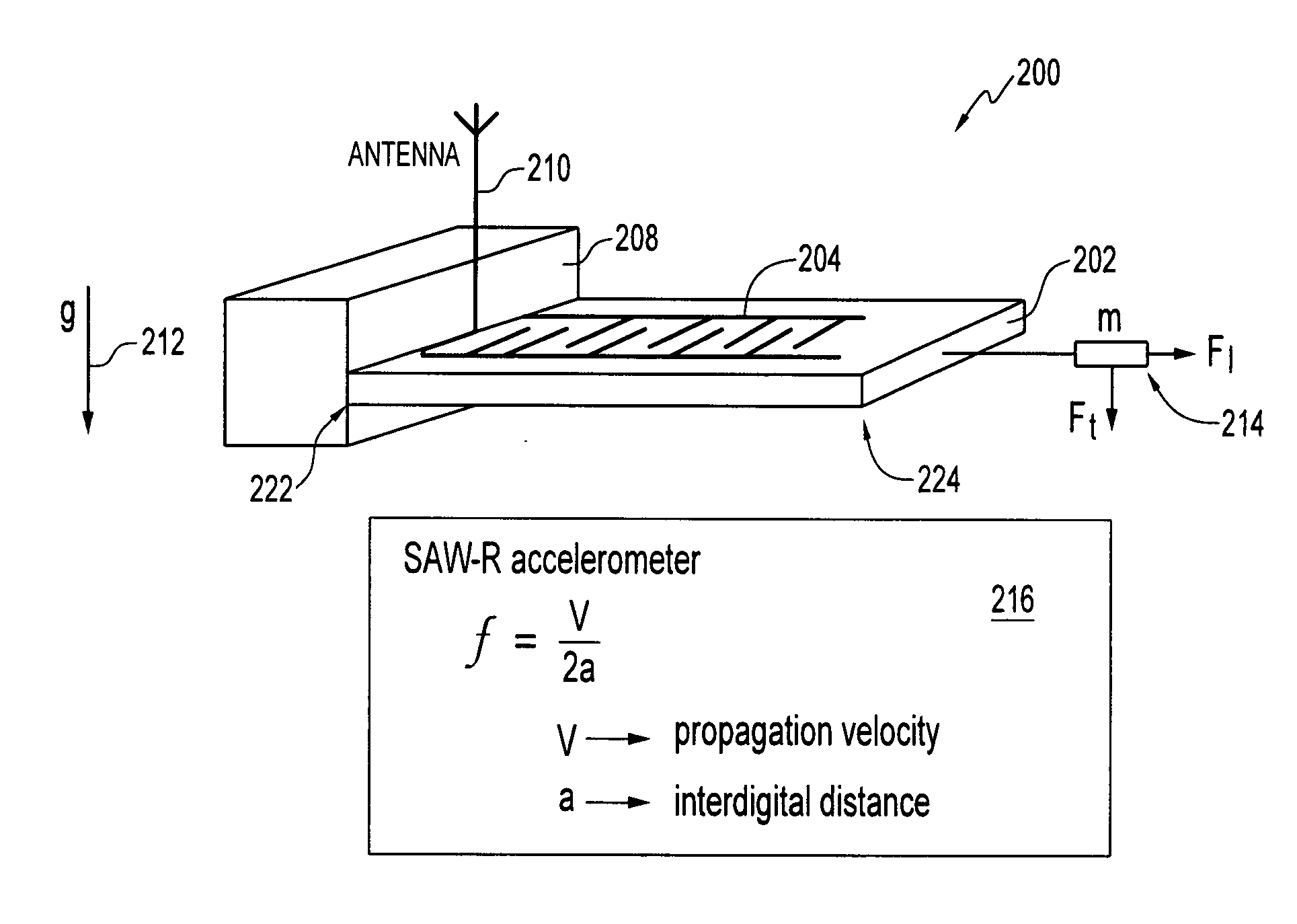
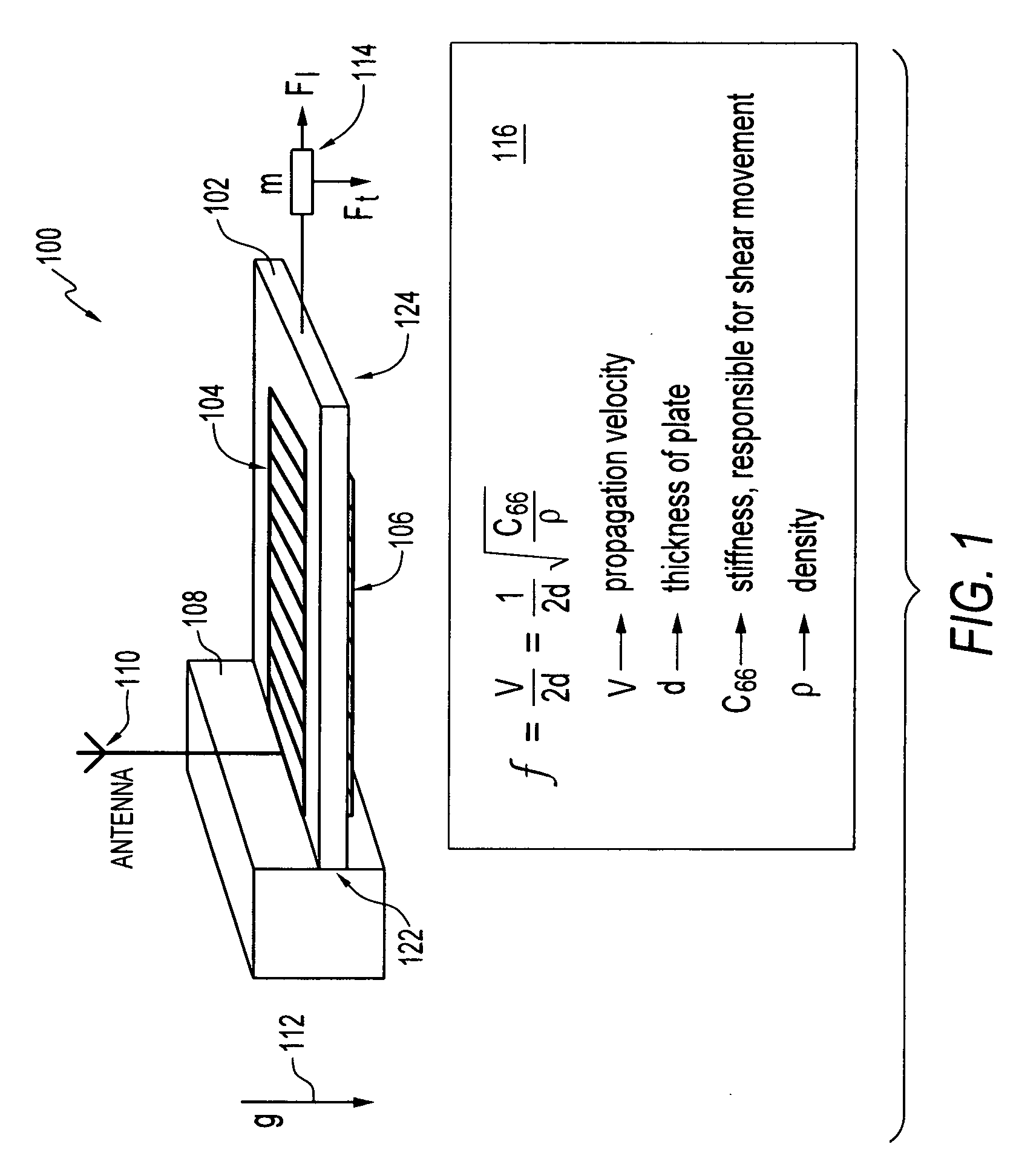
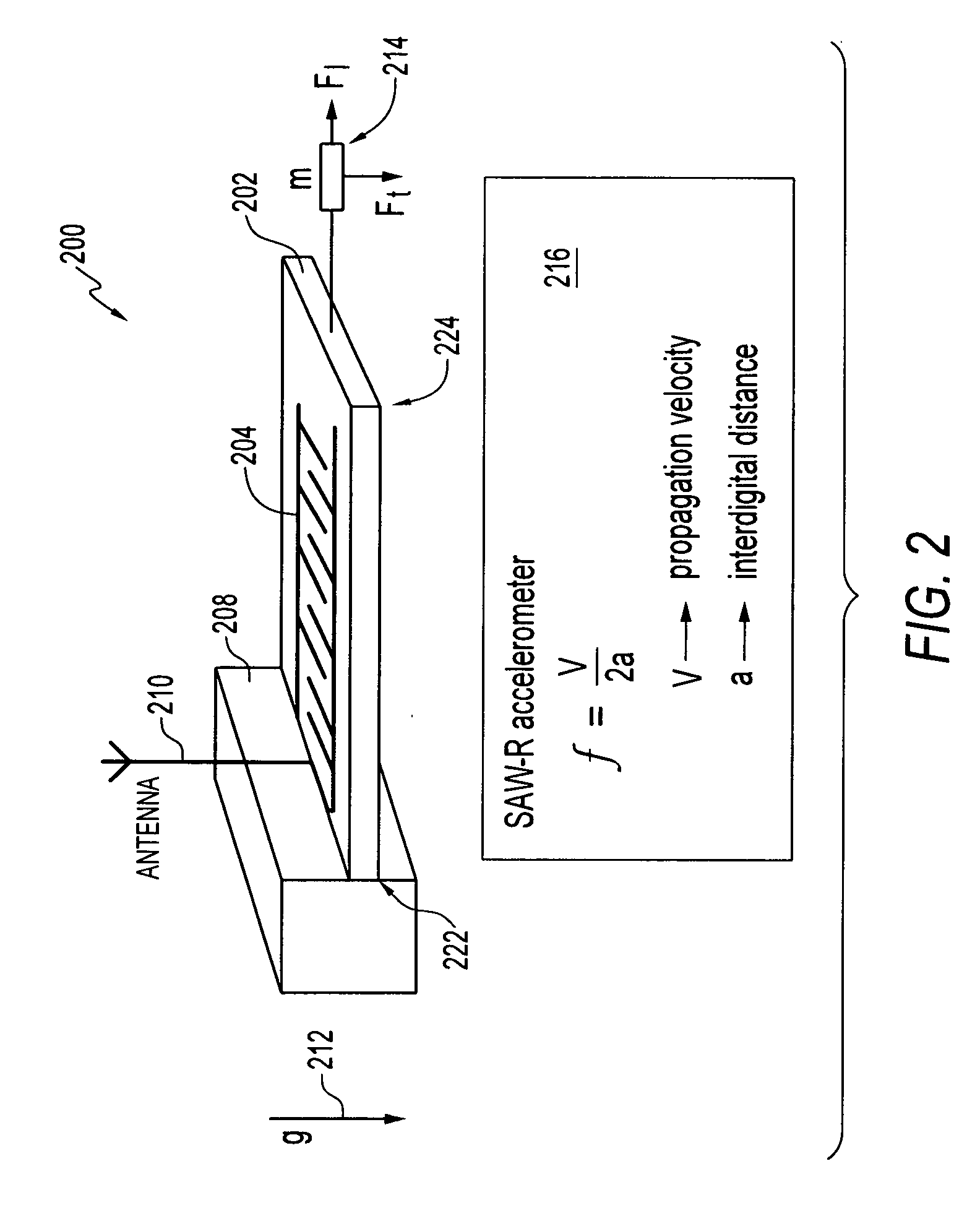
[0022]FIG. 1 illustrates a perspective view of a wireless and passive acoustic wave accelerometer 100 having a plurality of BAW (Bulk Acoustic Wave) electrodes 104 and 106, in accordance with one embodiment. The wireless and passive acoustic wave accelerometer 100 is generally formed from a piezoelectric substrate 102. Electrodes 104 and 106 are configured upon substrate 102. Each electrode 104, 106 comprise an interdigital transducer (IDT). The wireless and passive acoustic wave accelerometer 100 generally functions as an acceleration sensor or detector.
[0023] Piezoelectric substrate 102 can be formed from a variety of substrate materials, such as, for example, quartz, lithium niobate (LiNbO3), lithium tantalite (LiTaO3), Li2B4O7, GaPO4, langasite (La3Ga5SiO14), ZnO, and / or...
PUM
 Abstract
Description
Claims
Application Information