Dish rack with water drainage mechanism

Active Publication Date: 2006-12-21
SIMPLEHUMAN
View PDF25 Cites 34 Cited by
  • Summary
  • Abstract
  • Description
  • Claims
  • Application Information

AI Technical Summary

Benefits of technology

[0007] It is an object of the present invention to provide a dish rack t

Problems solved by technology

Unfortuately, these conventional dish racks suffer from several drawbacks.
First, they lack an effective way of draining the water collected on the base to the kitchen sink.
Tilting the base can be difficult (and dangerous) if the dish rack is fully loaded with dishes, bowls, utensils and other items.
Second,

Method used


Image

  • Dish rack with water drainage mechanism
  • Dish rack with water drainage mechanism
  • Dish rack with water drainage mechanism

Examples


Embodiment Construction

[0018] The following detailed description is of the best presently contemplated modes of carrying out the invention. This description is not to be taken in a limiting sense, but is made merely for the purpose of illustrating general principles of embodiments of the invention. The scope of the invention is best defined by the appended claims.

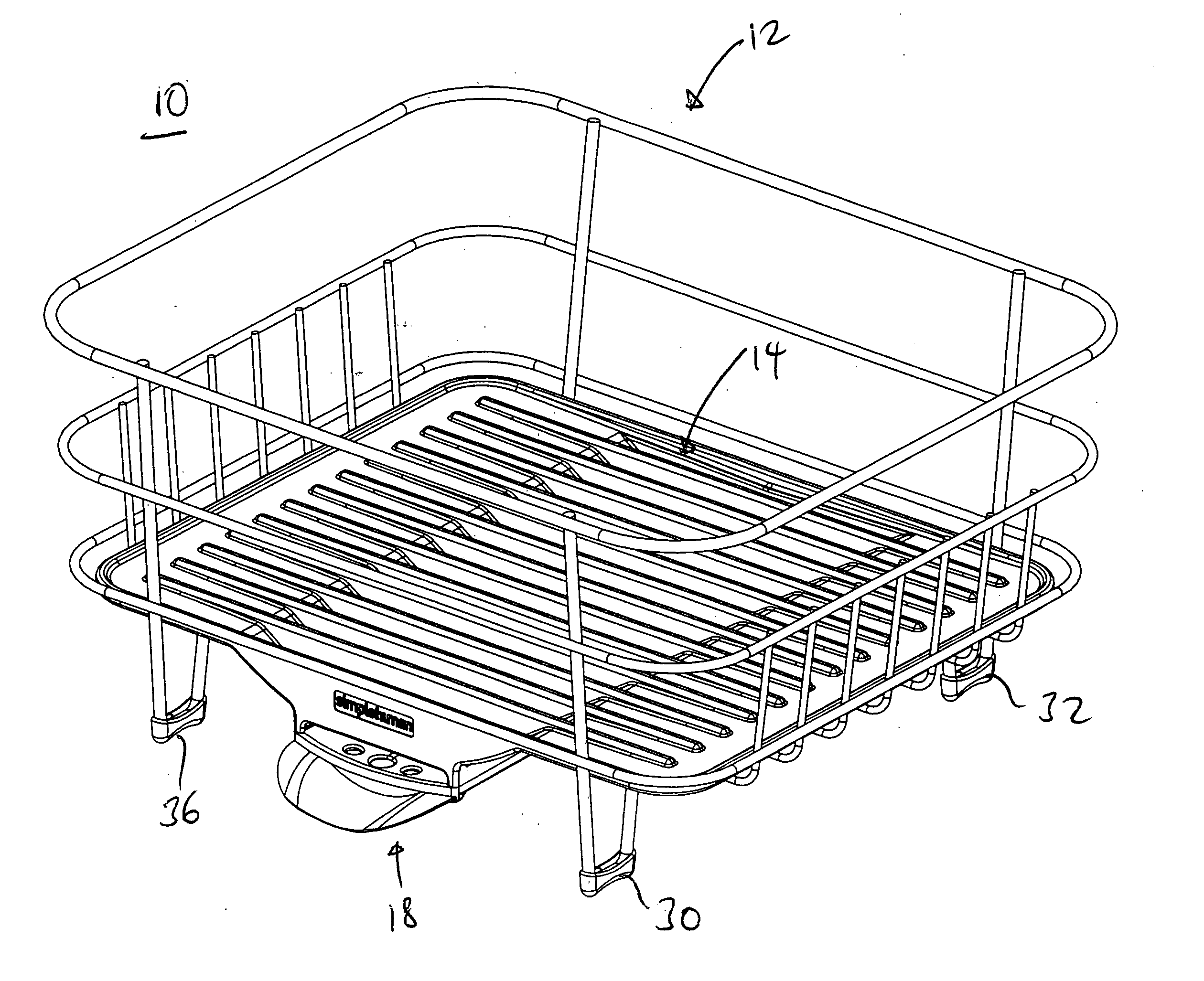
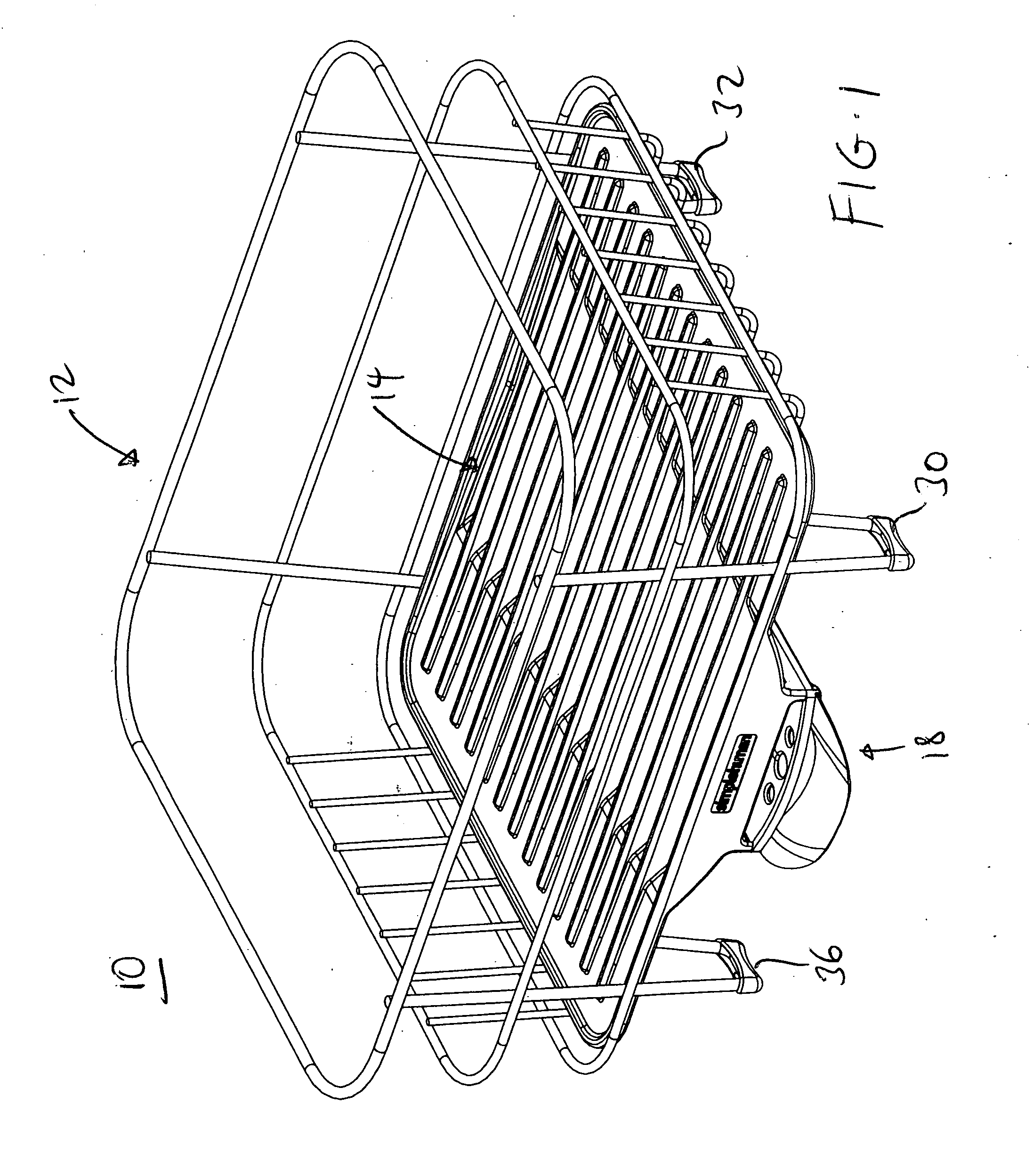
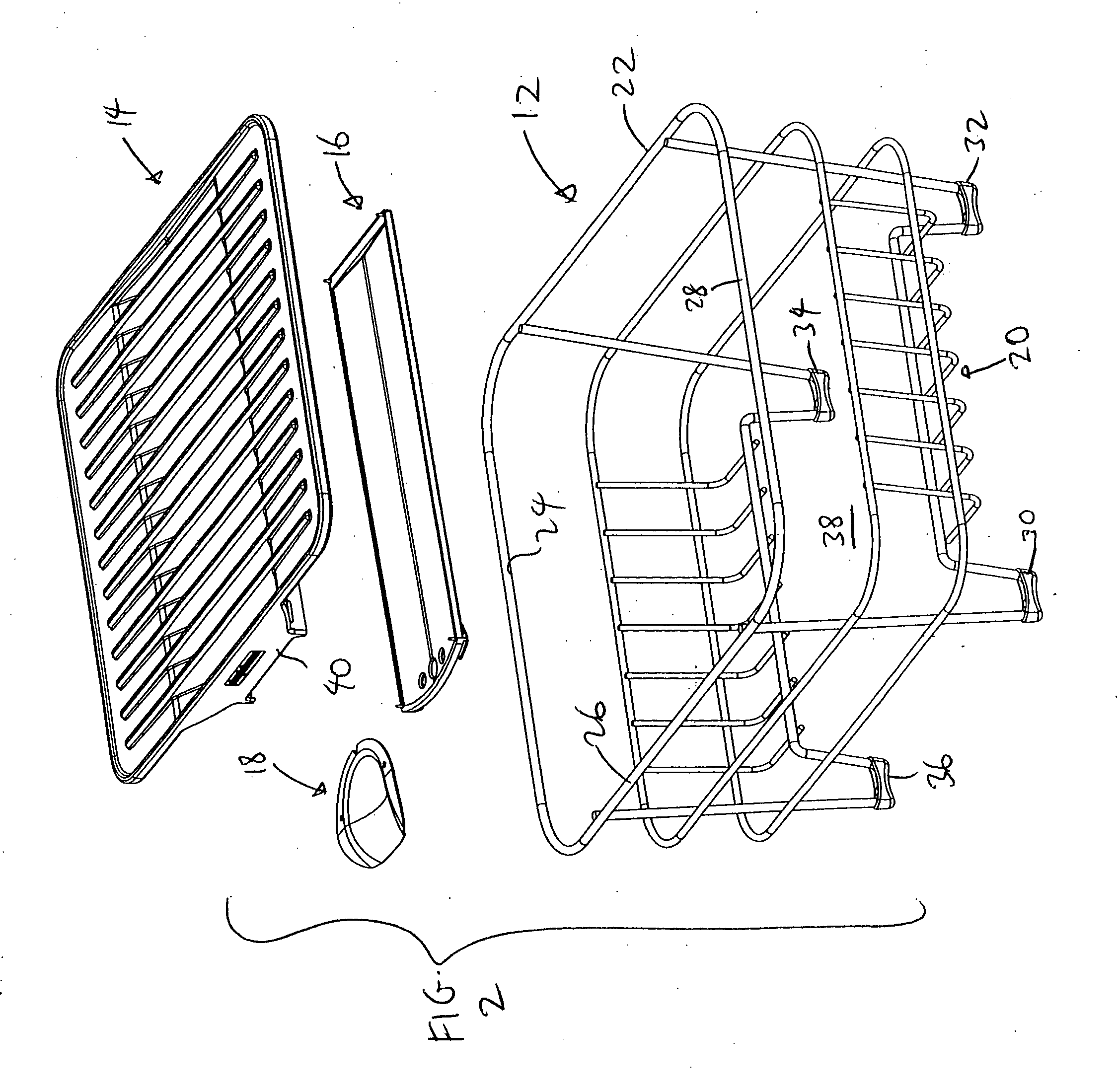
[0019]FIGS. 1-2 illustrate a dish rack 10 having a generally four-sided (e.g., square, rectangular) configuration. The dish rack 10 includes a wire frame 12, a tray 14, a ramp 16 and a spout 18. The wire frame 12 acts as a rack portion, and can be made of a metal wire frame that includes a wire frame base 20 and four wire frame walls 22, 24, 26, 28. Four legs 30, 32, 34, 36 are formed from the wire frame 12 and function to elevate the wire frame base 20 so that a trough 40 and the ramp 16 can be fitted below the wire frame base 20. The wire frame base 20 defines an opening 38 for receiving the central trough 40 of the tray 14.

[0020] Referring a...


PUM


Abstract

A dish rack has a rack portion having a tray, the tray having an opening. The dish rack also includes a ramp provided below the tray and positioned to receive water that flows through the opening of the tray. The ramp has a front end, a rear end, and a water outlet provided at the front end, the ramp being angled so that water flows from the rear end to the front end and then through the water outlet.

Description

BACKGROUND OF THE INVENTION [0001] 1. Field of the Invention [0002] The present invention relates to dish racks, and in particular, to a dish rack that can be used both adjacent, and inside, a kitchen sink. [0003] 2. Description of the Prior Art [0004] Dish racks are commonly used on kitchen countertops for positioning plates, bowls, cups and utensils to let them dry after they have been washed. The water from the washed plates, bowls, cups and utensils will typically drip on to the base or tray of the dish rack, and the water can be drained to the kitchen sink by tilting the base. In addition, the drip trays are sometimes used to hold or house plates, bowls and similar items. Thus, these drip trays serve a dual purpose: to hold / house these items, and to drain water. [0005] Unfortuately, these conventional dish racks suffer from several drawbacks. First, they lack an effective way of draining the water collected on the base to the kitchen sink. Tilting the base can be difficult (and...

Claims


Application Information

Patent Timeline
IPC IPC(8): A47G19/08
CPCA47L19/04
Inventor YANG, FRANKLUM, MYK WAYNEWEI, TZU-HAO
Owner SIMPLEHUMAN
Why Eureka
Try Eureka