Cooling heat exchanger
- Summary
- Abstract
- Description
- Claims
- Application Information
AI Technical Summary
Benefits of technology
Problems solved by technology
Method used
Image
Examples
first embodiment
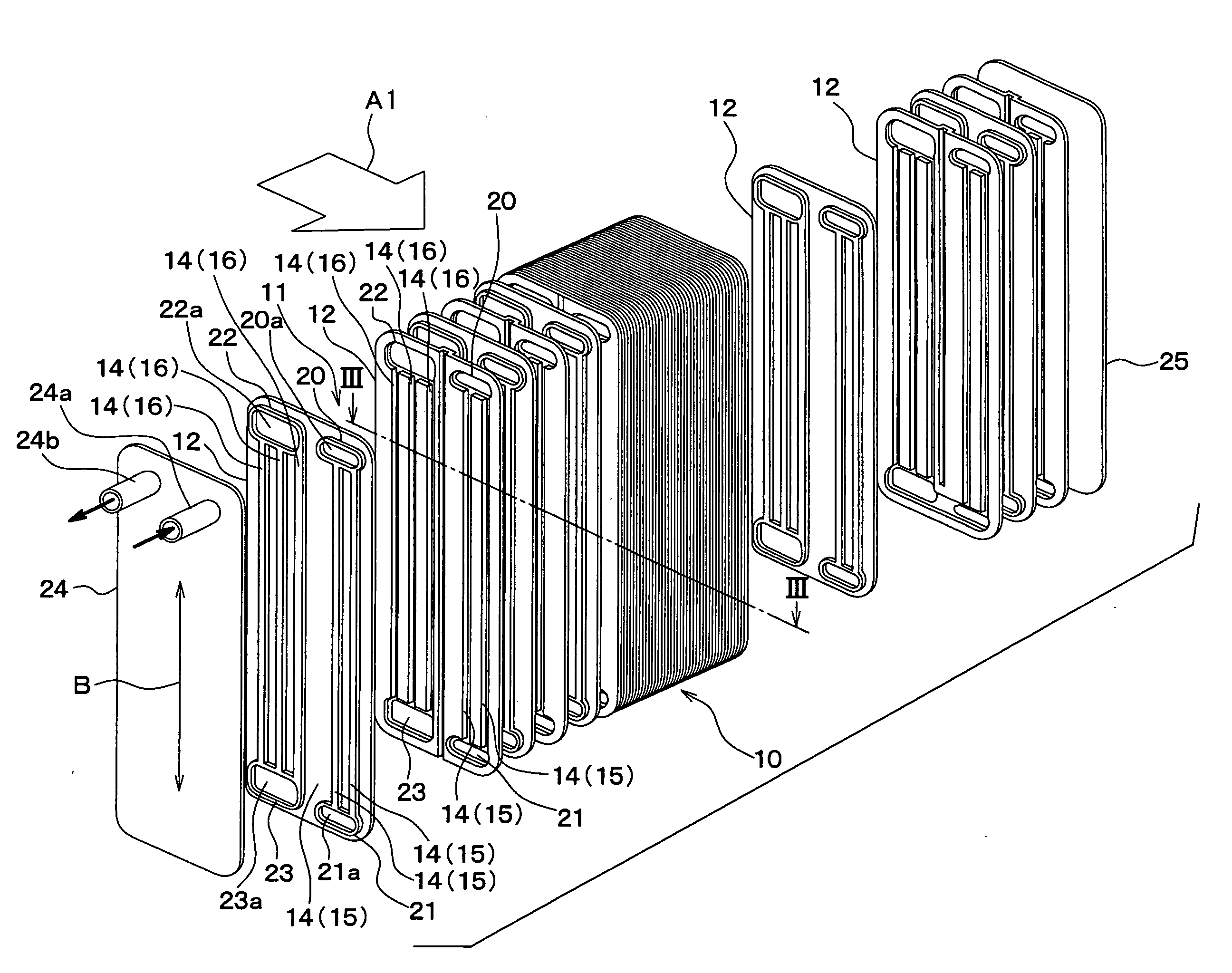
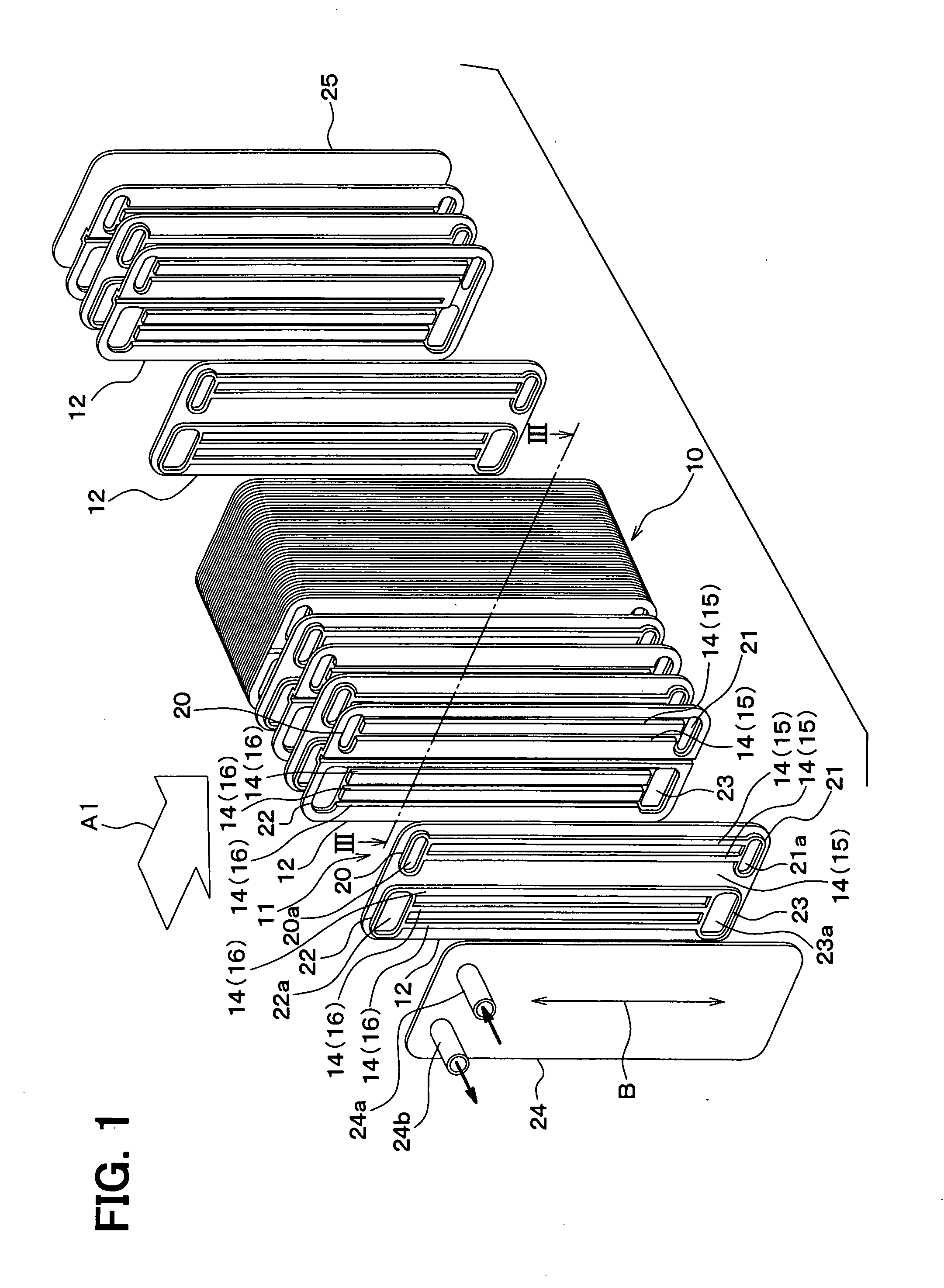
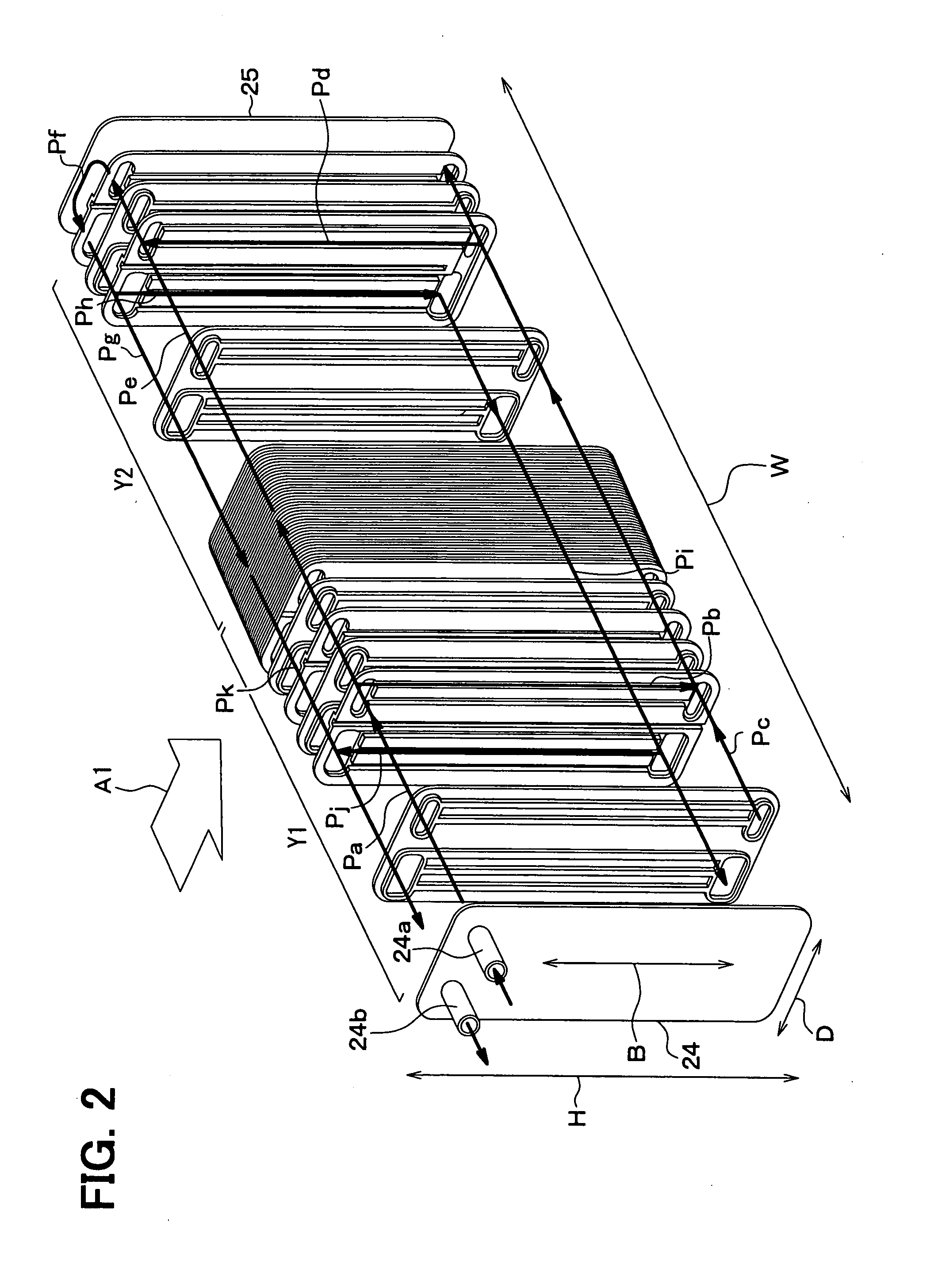
[0029]Referring to FIGS. 1 to 8, a heat exchanger of the first embodiment is exemplarily employed as an evaporator 10 for a vehicular air conditioner. A general structure of the evaporator 10 can be similar to a heat exchanger described in U.S. Pat. No. 6,047,769 (Japanese Unexamined Patent Publication No. 11-287580). The evaporator 10 generally includes a plurality of heat transfer plates 12.
[0030]In the drawings, arrows A1 denote a general flow direction of air for an air conditioning operation as an external fluid, and arrows B denote a general flow direction of an internal fluid, such as a refrigerant, flowing in internal fluid passages formed in heat transfer plates. The flow direction B of the refrigerant intersects the flow direction A1 of the air. In the illustrated example, the evaporator 10 is constructed as a perpendicularly countercurrent heat exchanger in which the flow direction A1 of the air is substantially perpendicular to the flow direction B of the refrigerant. Al...
second embodiment
[0125]The evaporator 10 according to the second embodiment is similar to the evaporator 10 of the first embodiment except a configuration of the offset wall 17a. In the first embodiment, the offset walls 17a are parallel to the plane of the base portions 13. In the second embodiment, on the other hand, the offset walls 17a are inclined relative to the plane of the base portions 13, with respect to the up and down direction.
[0126]As shown in FIG. 9, each of the offset walls 17a is inclined at a predetermined angle θa relative to the plane of the base portion 13 such that a distance between the offset wall 17a and the plane of the base portion 13 increases toward an upper position. As such, the condensation in the fin 17 of one heat transfer plate 12 is smoothly introduced into the fin 17 of the opposite heat transfer plate 12, as shown by the arrow N. Accordingly, the condensation is further smoothly drained.
third embodiment
[0127]The evaporator 10 according to the third embodiment is similar to the evaporator 10 of the first embodiment except a configuration of the offset wall 17a. In the third embodiment, the offset walls 17a are inclined relative to the plane of the base portions 13, with respect to the air flow direction A1, as shown in FIG. 10.
[0128]For example, each of the offset walls 17a is inclined in the same direction as a downstream side curved wall of the semi-circular-shaped protrusion 14. In other words, the off set wall 17a is inclined toward a downstream position with respect to the air flow direction A1. Specifically, the offset wall 17a forms an angle θb of inclination relative to the plane of the base portion 13 such that a distance between the offset wall 17a and the plane of the base portion 13 increases toward an upstream position with respect to the air flow direction A1.
[0129]In this case, the flow of the air is aligned along the downstream side curved wall of the protrusion 14 ...
PUM
 Abstract
Description
Claims
Application Information
 - R&D
- Intellectual Property
- Life Sciences
- Materials
- Tech Scout
- Unparalleled Data Quality
- Higher Quality Content
- 60% Fewer Hallucinations
Browse by: Latest US Patents, China's latest patents, Technical Efficacy Thesaurus, Application Domain, Technology Topic, Popular Technical Reports.
© 2025 PatSnap. All rights reserved.Legal|Privacy policy|Modern Slavery Act Transparency Statement|Sitemap|About US| Contact US: help@patsnap.com


