Control Panel

a control panel and control panel technology, applied in the field of control panels, can solve the problems of prone to wear and possible failure the internal of the device is not sealed, and the mechanical nature of the tilting mechanism is prone to wear and other problems, to achieve the effect of simple and robust assembly, and reducing the impact of the switch resistan

Active Publication Date: 2006-12-21
NEODRON LTD
View PDF16 Cites 88 Cited by
  • Summary
  • Abstract
  • Description
  • Claims
  • Application Information

AI Technical Summary

Benefits of technology

[0018] Where the sensing element comprises a resistive sensing path, the switch may include a deformable diaphragm, e.g. made of rubber, and having a resistivity which is substantially the same as that of the resistive sensing path. This can help reduce any impact of the resistance of the switch on the sensitivity and accuracy of the position sensing element in its vicinity.
[0019] For a one-dimensional position sensing element, i.e. one operable to determine the position of a touch in a single sensing direction, which may be arranged to follow a straight or curved path which may also be open or closed (e.g. rotary), the mechanical switch may be arranged to have a greater extent in a direction orthogonal to the sensing direction than in a direction along the sensing direction. This too can help reduce any impact of the switch on the sensitivity of the position sensing element in the vicinity of the switch.
[0020] The control panel may further comprise a substrate wherein the position sensing element and the mechanical switch are both mounted on the substrate. By providing the position sensing element and the mechanical switch with a common base, a simple and robust assembly is provided.
[0021] The control panel might further comprise a surface panel overlaying the position sensing element with an ope...

Problems solved by technology

This means the interior of the device is not sealed.
Accordingly, dirt and liquid may enter the device and caus...

Method used


Image

  • Control Panel
  • Control Panel
  • Control Panel

Examples


Embodiment Construction

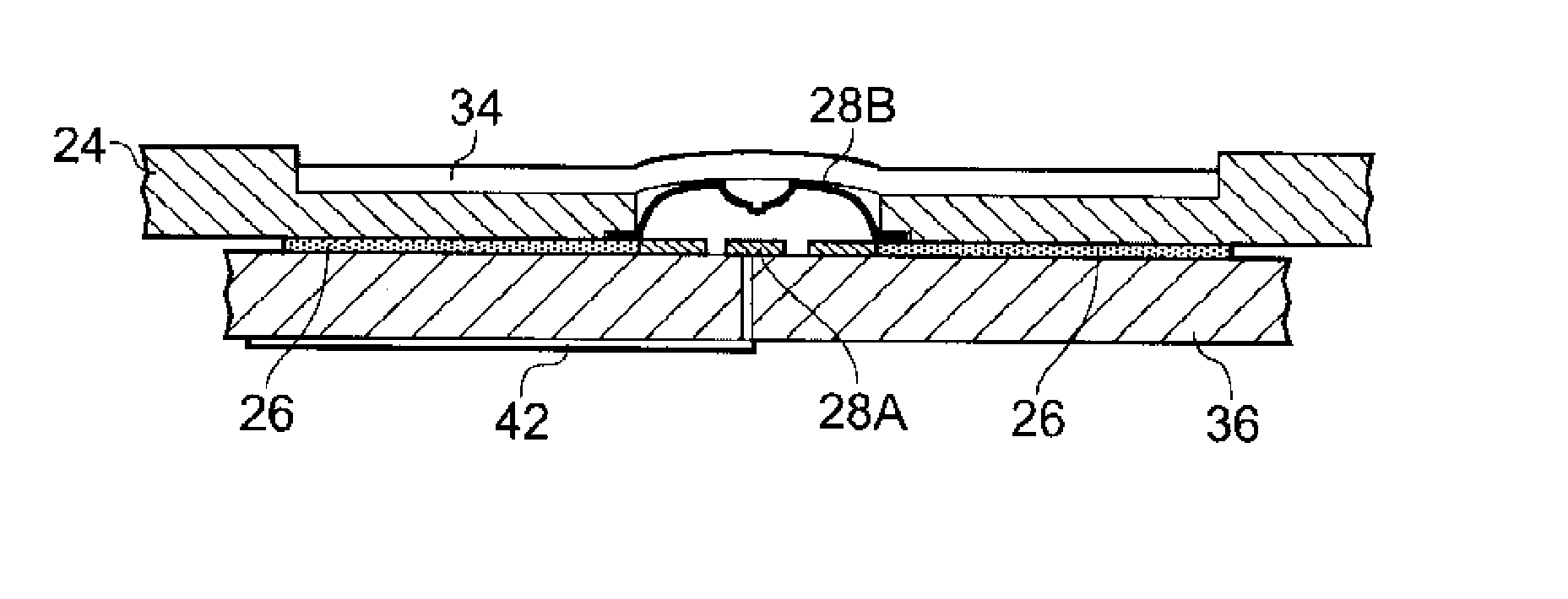
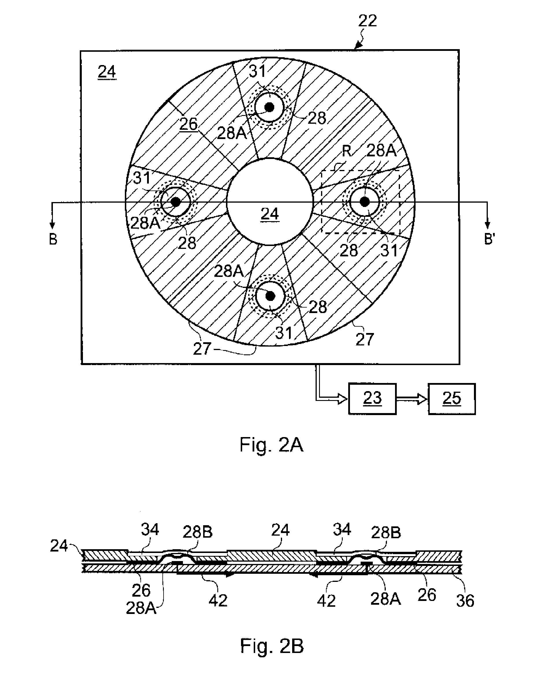
[0034]FIG. 2A schematically shows in plan view a control panel 22 for controlling a device, e.g. a portable music player, according to an embodiment of the invention. FIG. 2B schematically shows a section view of the control panel 22 taken along BB′. For the orientation shown in FIG. 2B, the control panel is operated from above. FIGS. 3A and 3B respectively show plan and section views of a region of the control panel 22 identified by a dashed line R in FIG. 2A on a larger scale.

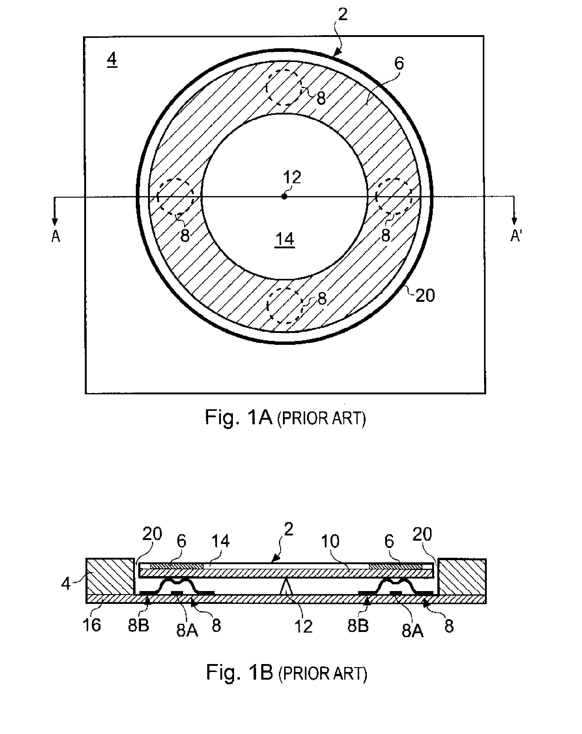
[0035] The control panel 22 has an overall level of functionality which is similar to the control panel 2 shown in FIGS. 1A and 1B in that it includes a position sensing element 26 in the form of a ring and four mechanical switches 28 (in this case dome-type push buttons).

[0036] The control panel 22 comprises a PCB substrate 36 carrying the position sensing element 26 and the mechanical switches 28, a surface panel 24 overlaying the substrate 36, and an outer protective flexible membrane 34. In this example...


PUM


Abstract

A control panel having a touch sensitive position sensor and at least one mechanical switch located within a sensitive area of the position sensor is provided. The position sensor comprises a capacitive position sensing element coupled to position sensing circuitry operable to determine the position of a capacitive load, such as a finger, positioned adjacent to the sensitive area of the position sensing element. The mechanical switch has an open state and a closed state and is arranged such that a contact of the switch is selectively electrically coupled to or decoupled from the position sensing element depending on whether the switch is in the open or closed state. A compact and robust control panel can thus be provided in which the presence of the mechanical switch within the sensitive area of the position sensor does not significantly effect its sensitivity.

Description

BACKGROUND OF THE INVENTION [0001] The invention relates to a control panel for controlling a device in response to a user's input, in particular the invention relates to a control panel having both touch sensitive and mechanical input means. [0002] There is an increasing demand for compact and user friendly control panels for many devices, for example for devices such as portable media players and so forth. These devices are becoming smaller and are being provided with more functionality. To make best use of this increased functionality it is important that the control panel presented to the user (i.e. the user interface) is ergonomic, is simple and intuitive to use, and allows the user to quickly access the functions of the device. There is also a demand for control panels which are both aesthetically pleasing and robust. [0003] It is known for control panels to include both touch sensitive inputs (e.g. capacitive position sensors) and mechanical inputs (e.g. conventional push but...

Claims


Application Information

Patent Timeline
IPC IPC(8): G09G5/00
CPCG06F3/044G06F3/03547G06F3/0448G06F3/0447
Inventor PHILIPP, HARALD
Owner NEODRON LTD
Why Eureka
Try Eureka