Display Device Operating in Sub-Field Process and Method of Displaying Images in such Display device

a display device and sub-field technology, applied in the field of display devices operating in sub-field processes and methods of displaying images in such display devices, can solve the problems of deteriorating display quality, deteriorating image display quality, and deteriorating images displayed by pseudo-framing lines, so as to reduce pseudo-framing lines and enhance gray scale characteristics

Inactive Publication Date: 2006-12-21
PANASONIC CORP
View PDF5 Cites 17 Cited by
  • Summary
  • Abstract
  • Description
  • Claims
  • Application Information

AI Technical Summary

Benefits of technology

[0071] In view of the above-mentioned problems in the conventional display devices, it is an object of the present invention to provide a display device and a method of displaying images both of which are capable of reducing pseudo-framing lines and enhancing gray scale characteristics.

Problems solved by technology

Pseudo-framing noise deteriorates display quality.
However, since the display device illustrated in FIG. 7A increases the number of gray scales and concurrently reduces the number of sub-fields, a pseudo-framing line significantly deteriorates images displayed.
However, the display device illustrated in FIG. 8 reduces the number Z of sub-field in displaying images, and hence, images are deteriorated by a pseudo-framing line.
In addition, since the number of gray scales is kept fixed, it would be difficult to distinguish a crow and the night darkness from each other in comparison with the display device illustrated in FIG. 7A.
In images displayed in a plasma display panel, a viewer can scarcely find a pseudo-framing line, even if images are moving.
However, in a scene having a low average picture level, such images displayed in a bright area scarcely move in such a speed that a pseudo-framing line is conspicuous.
In the display device illustrated in FIG. 8, it would not be possible to distinguish the crow and the night darkness from each other.

Method used


Image

  • Display Device Operating in Sub-Field Process and Method of Displaying Images in such Display device
  • Display Device Operating in Sub-Field Process and Method of Displaying Images in such Display device
  • Display Device Operating in Sub-Field Process and Method of Displaying Images in such Display device

Examples


first embodiment

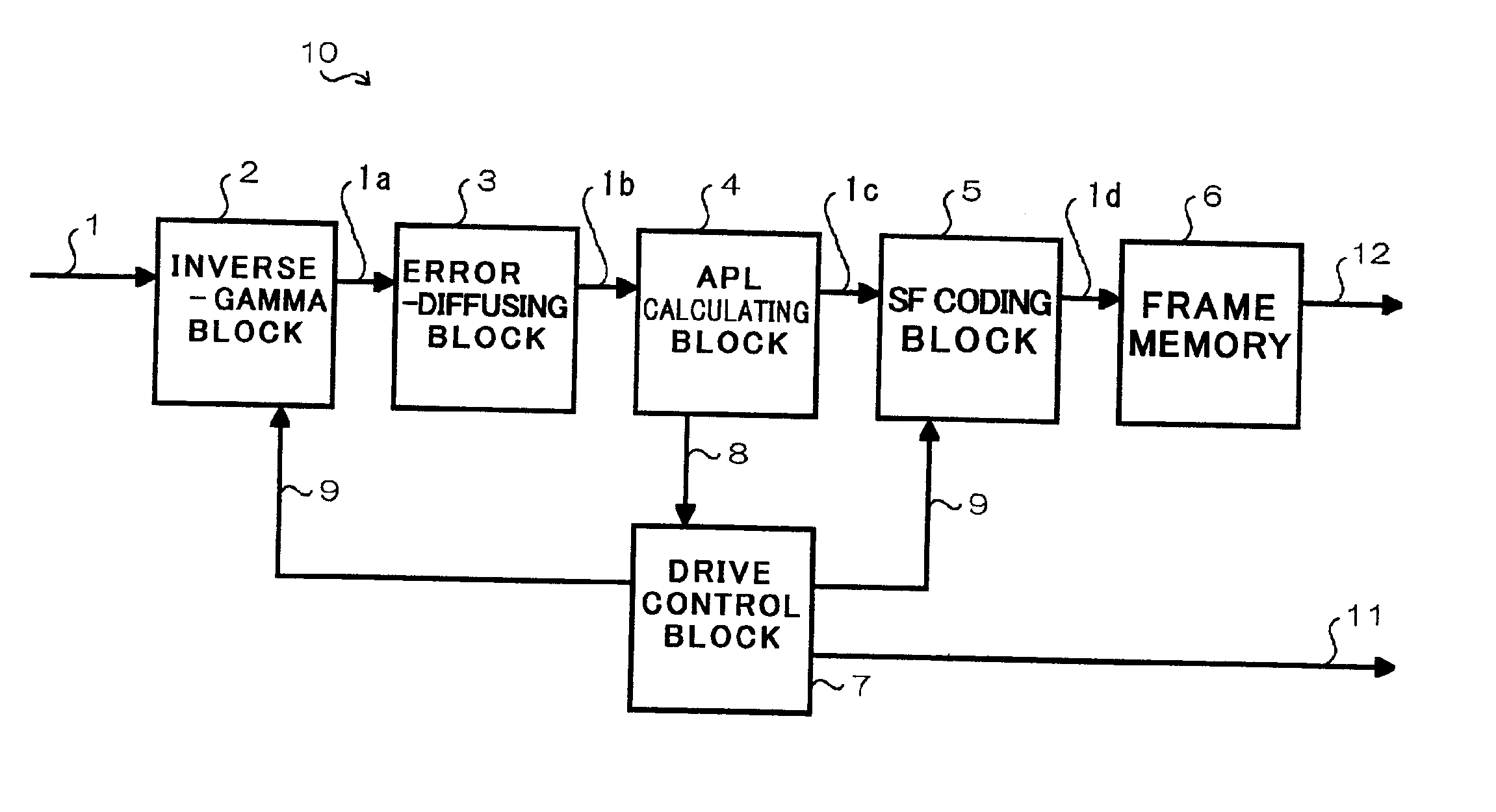
[0125]FIG. 9 is a block diagram of a display device 10 in accordance with the first embodiment of the present invention. The display device 10 in the first embodiment is applied to a plasma display panel (PDP).

[0126] As illustrated in FIG. 9, the display device 10 is comprised of an inverse-gamma block 2 which receives an image signal 1, applies inverse-gamma process to the received image signal 1, that is, changes the number of bits of the received image signal 1, and outputs at least one image signal 1a, an error-diffusing block 3 which receives the image signal 1a transmitted from the inverse-gamma block 2, and carries out error diffusion, that is, error-diffuses lower bits of the received image signal 1a, an APL calculating block 4 which receives an image signal 1b transmitted from the error-diffusing block 3, and calculates an average picture level (APL) of images indicated by the received image signal 1b, a sub-field coding block 5 which receives an image signal 1c transmitte...

second embodiment

[0164] In the above-mentioned first embodiment, the number of sub-fields to be displayed in a plasma display panel is determined to be fixed. As an alternative, a difference between the number 9 of sustaining pulses and the number of bits of a signal to be sub-field coded may be determined to be fixed, which suppresses generation of a pseudo-framing line to some degree.

[0165] However, if the number of sub-fields is increased, it would be necessary to shorten a period of scanning time for writing lower bits in order to prevent an increase in a period of writing time. This might result in an increase in writing defectiveness. In order to keep balance between writing defectiveness and prevention of generation of pseudo-framing lines, it would be necessary to determine the number of sub-fields to be determined when the number of sustaining pulses is relatively great, to be equal to or greater than the number of sub-fields to be determined when the number of sustaining pulses is relativ...


PUM


Abstract

A display device operating in accordance with a sub-field process, includes a first block which varies the number of bits of a received image signal, a second block which calculates an average picture level (APL) of images defined by the image signal transmitted from the first block, a third block which converts the image signal into sub-field coding data, and outputs the sub-field coding data to a display panel, and a fourth block which receives the average picture level from the second block, converts the received average picture level to the number of sustaining pulses, transmits the number of sustaining pulses to the display panel, and transmits the number of sustaining pulses to the third block, wherein the third block selects the number of bits of a signal to be input thereinto, in accordance with the number of sustaining pulses received from the fourth block.

Description

CROSS-REFERENCE TO RELATED APPLICATION [0001] This is a continuation of application Ser. No. 10 / 410,438 filed Apr. 10, 2003. The entire disclosure of the prior application, application Ser. No. 10 / 410,438 is hereby incorporated herein by reference.BACKGROUND OF THE INVENTION [0002] 1. Field of the Invention [0003] The invention relates to a display device such as a display device including a plasma display panel or a digital micro-mirror device, and a method of displaying images in such a display device. [0004] 2. Description of the Related Art [0005] Hereinbelow is explained how an image signal is processed in a plasma display panel as a typical example of a digital display device. [0006]FIG. 1 is a block diagram showing how an image signal is processed in a conventional plasma display panel. [0007] The illustrated plasma display panel is comprised of a first block 62 which receives an image signal 61, and applies inverse-gamma process to the received image signal 61, a second bloc...

Claims


Application Information

Patent Timeline
Patent Type & Authority Applications(United States)
IPC IPC(8): G09G5/10G09G3/20H01L51/50G09G3/291G09G3/294G09G3/296G09G3/30G09G3/34H04N5/66
CPCG09G3/2022G09G3/2051G09G3/2062G09G2360/16G09G2320/0261G09G2320/0266G09G3/2803G09G3/296
Inventor KIMURA, TOHRU
Owner PANASONIC CORP
Why Eureka
Try Eureka