LED display screen control system

A technology of LED display screen and control system, which is applied in the direction of static indicators, instruments, etc., can solve problems such as unfavorable high-density small-pitch LED display design, difficulty in testing LED display screens, and failure to meet display effect requirements, etc., to achieve improved display effect, reduce the number of cable cores, and monitor stable and reliable effects

Active Publication Date: 2017-05-31
XIAN NOVASTAR TECH
View PDF5 Cites 9 Cited by
  • Summary
  • Abstract
  • Description
  • Claims
  • Application Information

AI Technical Summary

Problems solved by technology

[0005] However, in the existing LED display control system, the connection between the scanning card and the HUB board increases the thickness of the product, which is not conducive to the design of high-density small-pitch LED display
The scanning card drives multiple LED light board modules, but it is difficult to support a large loading area due to the limitation of the bandwidth of the scanning card
Furthermore, because of its low price, the general-purpose driver chip is still favored by customers even though it has been used for a long time. For the LED cabinet of the general-purpose chip, due to its driving characteristics, it is necessary to output grayscale data continuously. However, the RGB data set output by the FPGA is limited, which cannot meet the occasions where the display effect is relatively high.
In addition, since the scanning card and the LED light board module are connected by cables, the existing signal transmission and connection methods have the following problems: 1) Each single-ended signal needs to occupy a core, resulting in the The number of cores is large. Taking a conventional 8-scan LED light board module as an example, if two sets of RGB data are required, plus clock signal (CLK), latch signal (LAT), enable signal (OE), and row selection signal (A, B, C) and other signals have a total of 12 single-ended signals, plus at least one ground signal, at least 13-core cable is required. However, there are often some applications in the LED display industry that connect LED light board modules The number of wire cores entering the cable is limited, and multi-core cable is inconvenient; 2) Due to the large number of cable cores, there are many contact points between the cable and the connector between the LED light board module, and a single core Impairment or poor contact will lead to abnormal display, which accounts for a large proportion of LED display application failures; 3) TTL signal transmission distance is limited due to signal attenuation, usually no more than 2 meters, some applications need to be replaced Long transmission distance, so TTL signal is not competent; and 4) The transmission of TTL signal by cable leads to large signal radiation, which makes it difficult for LED display screens to pass EMC tests

Method used


Image

  • LED display screen control system
  • LED display screen control system
  • LED display screen control system

Examples


Embodiment Construction

[0025] In order to make the above objects, features and advantages of the present invention more comprehensible, specific implementations of the present invention will be described in detail below in conjunction with the accompanying drawings.

[0026] Specifically, the following embodiments of the present invention propose a new LED display control system solution, in order to solve the problems in the existing LED display control system, reduce the volume of the scanning card, support large load, and support high density and small spacing LED display body; at the same time solve the problem of poor display effect of the existing scanning card in the universal driver chip LED display body, improve the display effect of the screen body; and reduce the number of cables by using a new transmission method, Improve the stability and reliability of transmission, reduce EMI, and meet EMC requirements more easily.

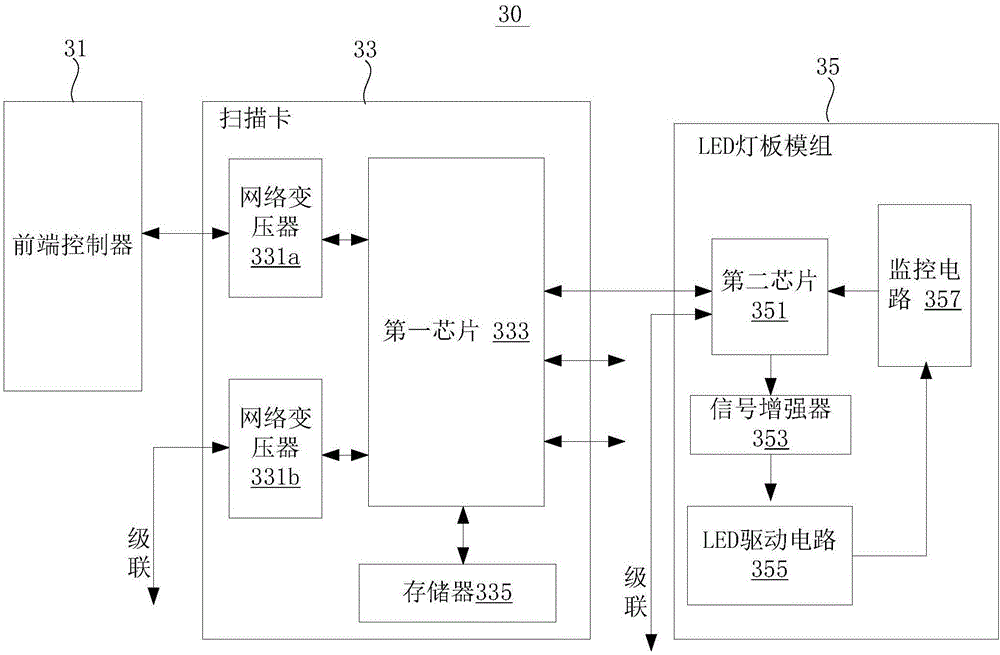
[0027] see image 3 , which is a schematic diagram of an LED displa...


PUM


Abstract

The invention provides an LED display screen control system (30). The LED display screen control system comprises a front-end controller (31), an LED lamp panel module (35), and a scanning card (33) connected between the front-end controller (31) and the LED lamp panel module (35), wherein the scanning card (33) comprises a first chip (333), and the LED lamp panel module (35) comprises a second chip (351); the first chip (333) is used for receiving and unpacking a data packet coming from the front-end controller (31), processing the image data obtained by unpacking the data packet, and repacking the processed image data, so that the processed image data packet is obtained, output and transmitted to the second chip (351) of the LED lamp panel module (35) in the differential signal manner; the second chip (351) is used for receiving and unpacking the processed image data packet coming from the first chip (333), and generating a control signal and a display data set according to the image data obtained by unpacking the processed image data packet, wherein the control signal and the display data set are transmitted to an LED drive circuit (355) on the LED lamp panel module (35) for carrying out display drive. Therefore, with the LED display screen control system, the problem that the signal transmission stability between the LED lamp panel module and the scanning card is poor is solved.

Description

technical field [0001] The invention relates to the field of display technology, in particular to an LED display screen control system. Background technique [0002] The existing LED display control system mainly includes a sending card, a scanning card and an LED display, where the scanning card is configured in each LED cabinet (including one or more LED light board modules), and multiple LED cabinets are spliced into an LED display. The display effect of the LED display is directly determined by the scanning card (or LED display control board, receiving card) configured in each LED cabinet. When the specifications of the LED box are determined, the performance parameters of the LED display are basically determined, especially in the general-purpose driver chip LED display. [0003] Such as figure 1 As shown, the signals transmitted between the scanning card and the LED light board module in the existing LED display control system and the LED light board module and the ...

Claims


Application Information

Patent Timeline
Patent Type & Authority Applications(China)
IPC IPC(8): G09G3/32
CPCG09G3/32
Inventor 王伙荣刘德福
Owner XIAN NOVASTAR TECH
Why Eureka
Try Eureka