
Print head cap

Active Publication Date: 2006-12-21
BROTHER KOGYO KK
View PDF2 Cites 0 Cited by
  • Summary
  • Abstract
  • Description
  • Claims
  • Application Information

AI Technical Summary

Benefits of technology

[0008] A print head cap is disclosed herein, in which air-tightness can be retained while the yield in manufacturing can be improved.

Problems solved by technology

However, since the cap is formed out of an elastic body of rubber or the like, it is difficult to manufacture the cap particularly into such a high-precision shape.
Thus, it is difficult to retain air-tightness required in the cap.
In addition, since defective caps are often manufactured, there is also a problem that the yield in manufacturing deteriorates.

Method used


Image

  • Print head cap
  • Print head cap
  • Print head cap

Examples


Embodiment Construction

[0023] Embodiments of the invention will be described below in detail with reference to the drawings.

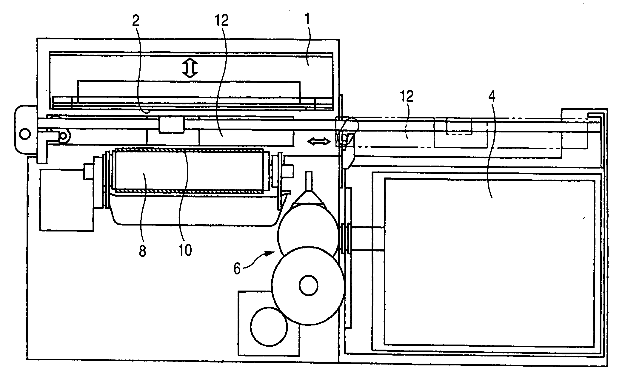
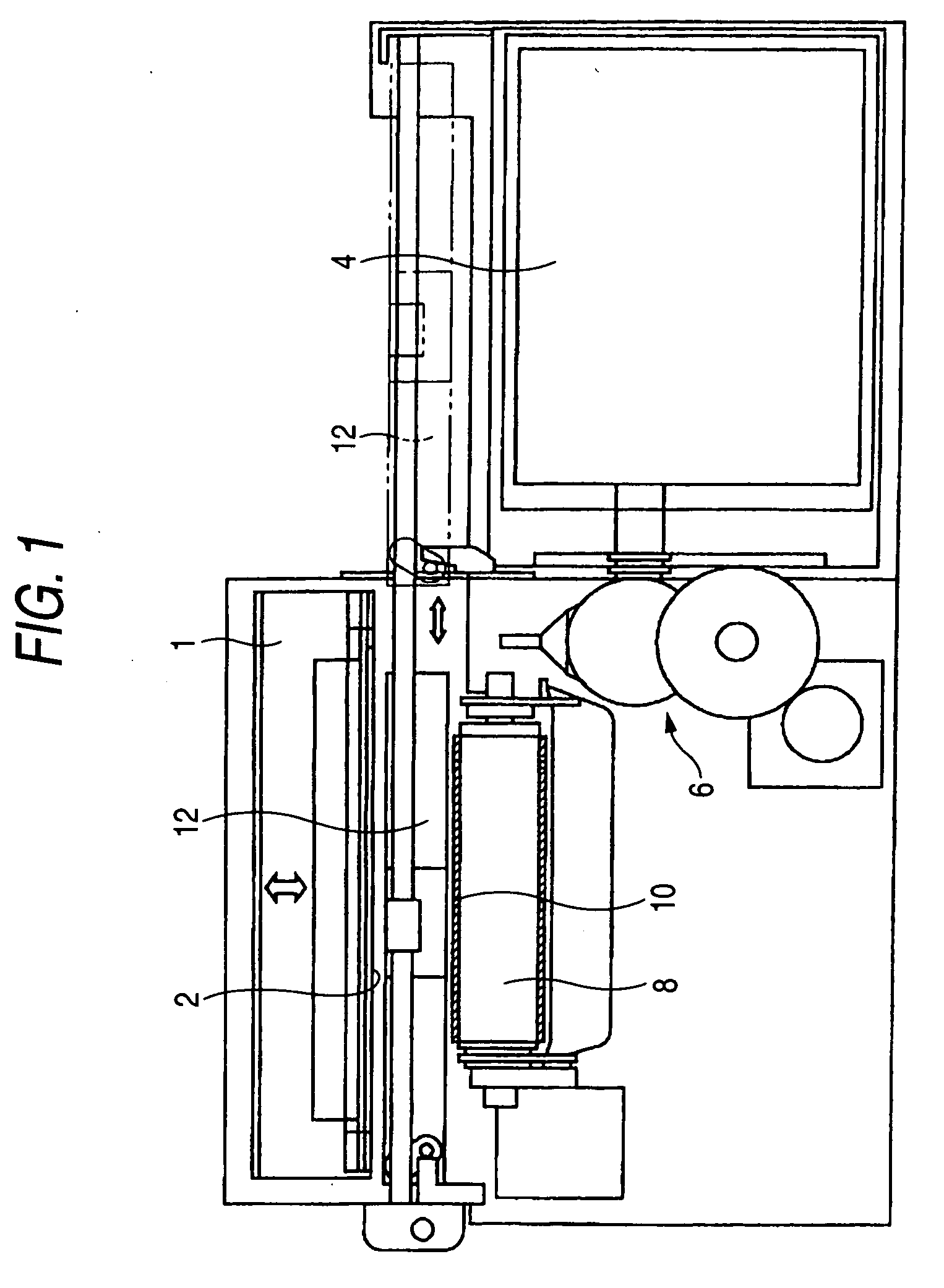
[0024] As shown in FIG. 1, a printer according to this embodiment has a full-line type print head 1, and a large number of not-shown nozzles are formed in the print head 1 in a direction perpendicular to the direction of feeding printing paper. A nozzle surface 2 in which the nozzles are opened is disposed to be opposed to the printing paper.

[0025] In addition, the print head 1 is of an ink jet system for ejecting ink droplets onto the printing paper. For example, such a print head 1 is provided for respective colors of yellow, magenta, cyan and black. Incidentally, each part of the print head 1 is supplied with its corresponding color ink from an ink cartridge 4 through an ink supply mechanism 6.

[0026] The printing paper is fed in tight contact with the surface of a belt 10 laid between a pair of rollers 8 (only one of which is shown). Each print head 1 is disposed in a body case...


PUM


Abstract

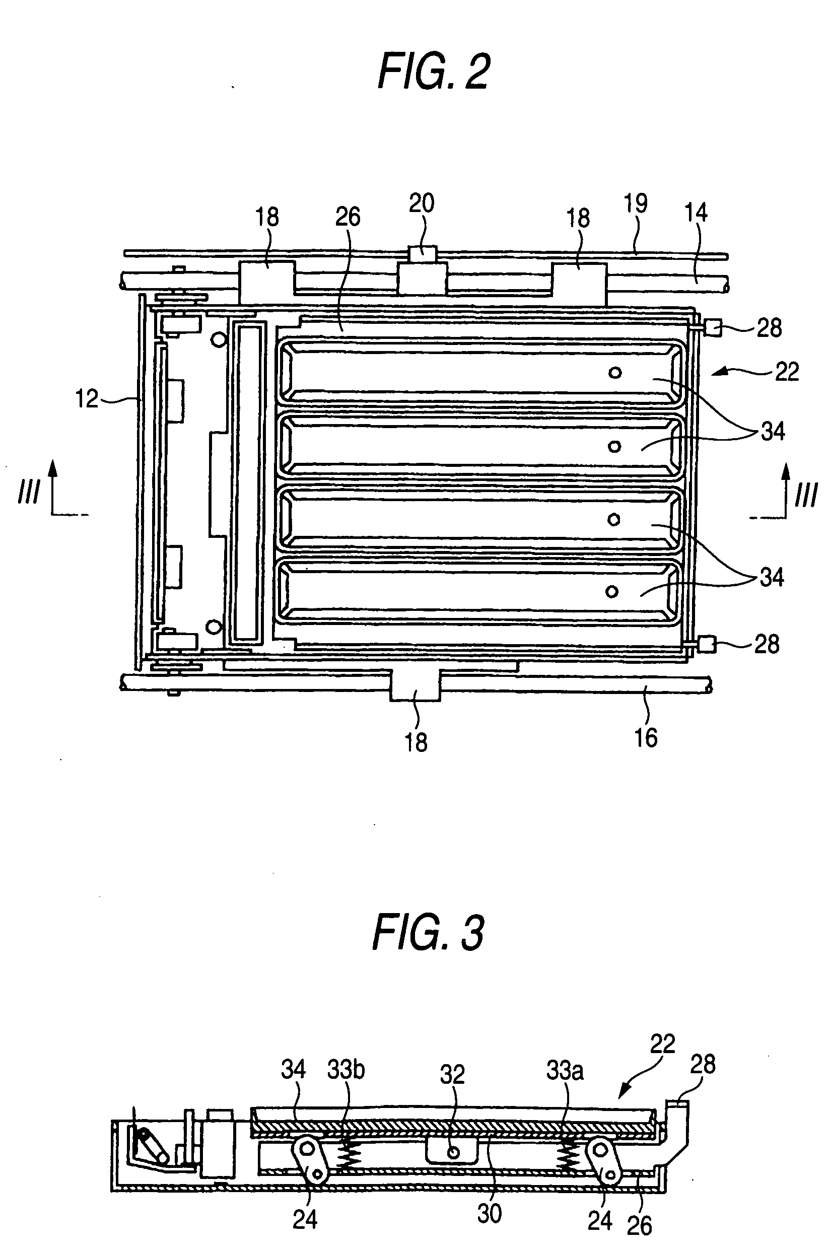
A print head cap includes a bottom surface; and a ring-like lip. The ring-like lip surrounds the bottom surface, protrudes toward a nozzle surface of a print head of an ink jet printer and is elastically deformable. The ring-like lip is pressed onto the nozzle surface to cover the nozzle surface therewith. The ring-like lip has corners that change the direction surrounding the bottom surface. The corners of the ring-like lip are more elastically deformable than the other portions of the ring-like lip.

Description

[0001] This is a Divisional of application Ser. No. 10 / 809,341 filed Mar. 26, 2004. The entire disclosure of the prior application is hereby incorporated by reference herein in its entirety.BACKGROUND OF THE INVENTION [0002] 1. Field of the Invention [0003] The present invention relates to a print head cap for covering a nozzle surface therewith at the time of recovering a print head for ejecting ink droplets onto printing paper or at the time of keeping the print head moist. [0004] 2. Background Art [0005] In the related art, as disclosed in JP-A-5-193150, there has been known a cap having a box-like sealing portion, a thick portion formed in the outer circumference of the sealing portion and a thin portion coupling the sealing portion with the thick portion. In order to improve the sealing performance of the cap pressed onto the nozzle surface of a print head, the cap is adapted so that the thin portion is deformed when the sealing portion is pressed onto the nozzle surface, so th...

Claims


Application Information

Patent Timeline
IPC IPC(8): B41J2/165
CPCB41J2/16508
Inventor NAKASHIMA, ATSUHISA
Owner BROTHER KOGYO KK
Learn More