
Controlling the angular extent of autostereoscopic viewing zones

a technology of viewing zone and angular extent, applied in optics, instruments, electrical equipment, etc., can solve the problems of affecting the performance of panoramagrams commercially available in both scenarios, and affecting the quality of comparison images

Active Publication Date: 2006-12-21
REAID INC
View PDF49 Cites 56 Cited by
  • Summary
  • Abstract
  • Description
  • Claims
  • Application Information

AI Technical Summary

Benefits of technology

[0010] According to one aspect of the present design, there is provided a method and system for providing an ability to alter an angular extent of a panoramagram viewing zone received from a display having a first quantity of columns of data associated therewith. The design comprises providing a first column of data having a baseline number of views associated therewith, said first column of data provided to at least one lenticule in a lens sheet associated with the display. The design further comprises altering the first quantity of columns of data to a second quantity of columns of data provided to the at least one lenticule. The second quantity of columns comprises more views than the baseline number of views. Employing the second quantity of columns when constructing an autostereoscopic image provides a display having relatively clear viewing of autostereoscopic images for specific viewing distances.

Problems solved by technology

Beyond the nth order zone, comparative image quality tends to significantly degrade.
Such restriction of movement is both uncomfortable and undesirable.
Currently no panoramagrams commercially available perform well in both scenarios.
Previously available designs therefore have issues with variance in viewer position relative to the display.

Method used


Image

  • Controlling the angular extent of autostereoscopic viewing zones
  • Controlling the angular extent of autostereoscopic viewing zones
  • Controlling the angular extent of autostereoscopic viewing zones

Examples


Embodiment Construction

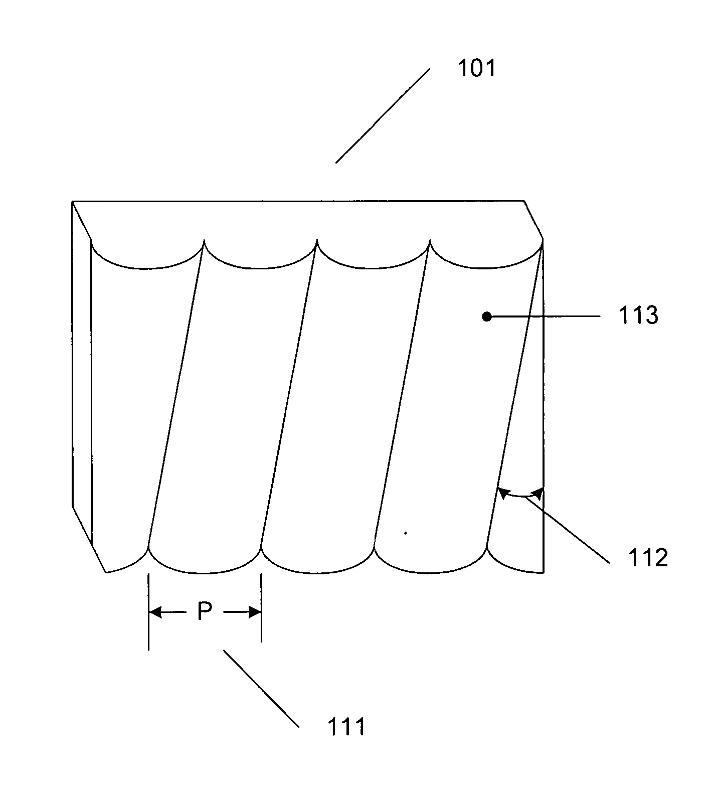
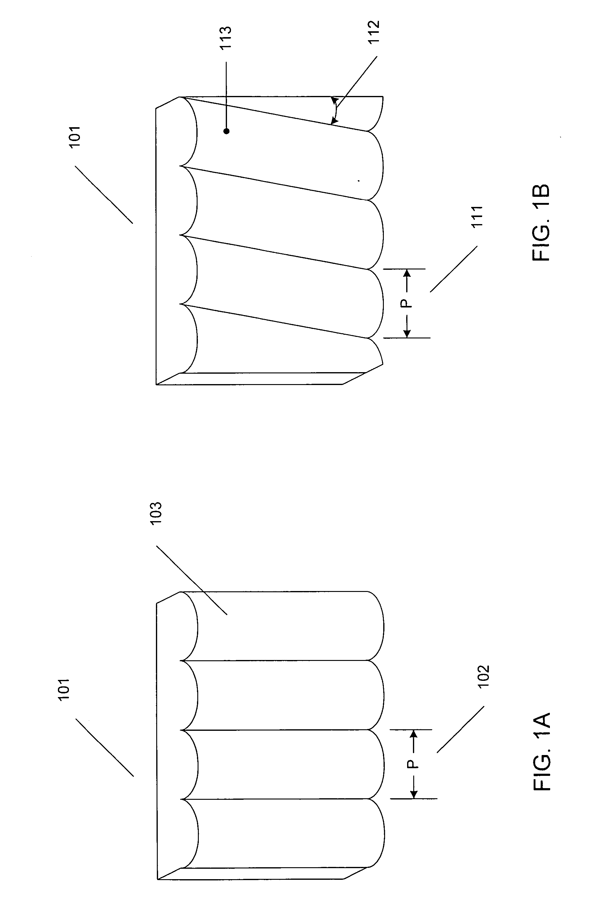
[0019] The present design uses refractive semi-cylindrical lenticules of the types shown in FIGS. 1A and 1B. In such a construction, two related types of lens sheets are available, both having similar characteristics. Lenticular sheets or raster barriers enable viewing of a stereoscopic image without the use of individual selection devices (glasses) worn by the observer, and are optically interchangeable. The present teachings apply to both types of selection devices.

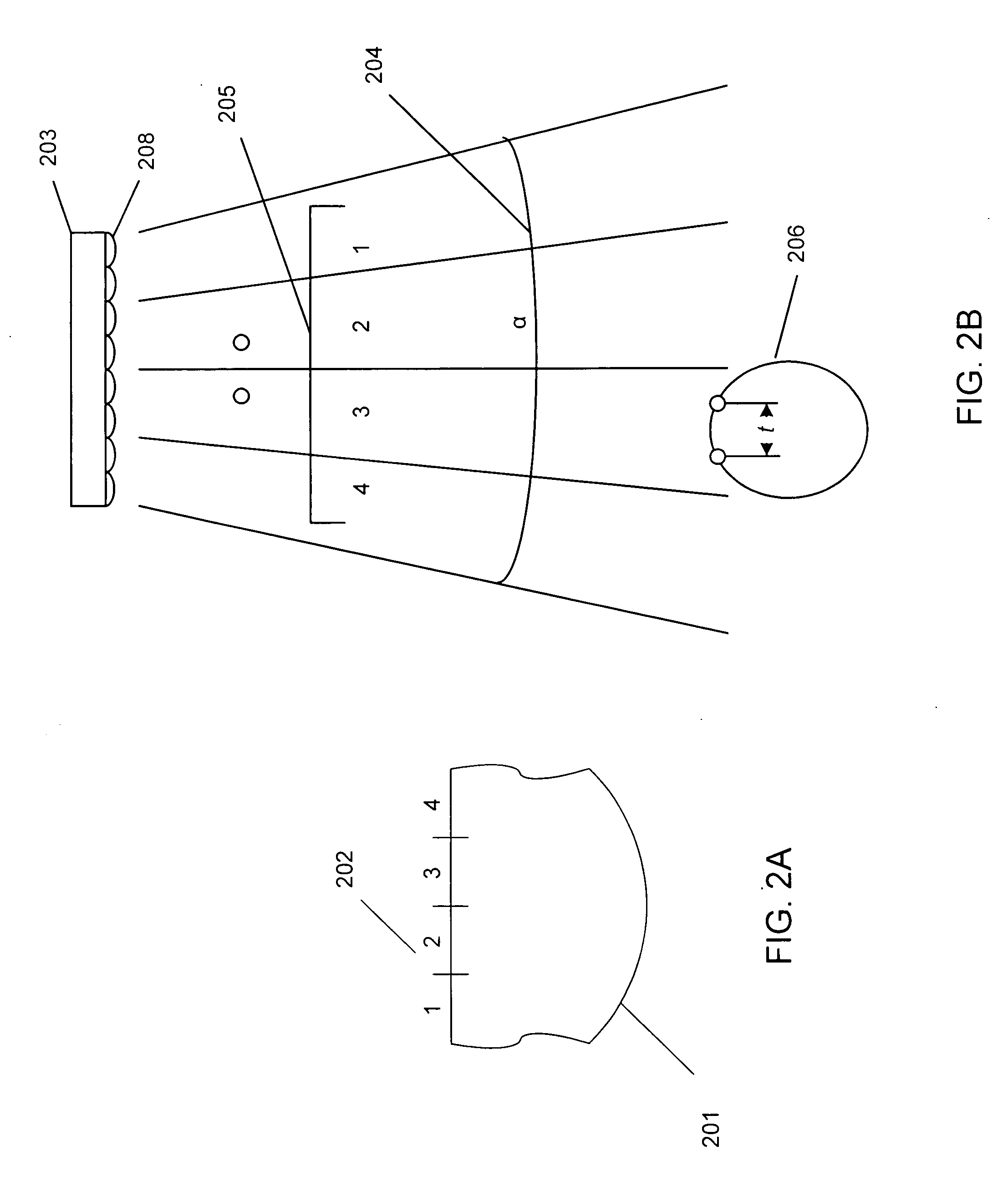
[0020] In order to see an autostereoscopic image, the observer must be within a certain distance range from the display, not too close and not too far. From too far a distance, the observer will see views with reduced perspective differences, as can be seen by comparing FIGS. 2B and 3B, as will be discussed more fully below. The strength of the stereoscopic depth effect is proportional to the interaxial separation between camera locations, said cameras existing in the visual world or a computer universe. The perspectiv...


PUM


Abstract

A method and system for providing an increased angular extent of autostereoscopic viewing zones received from a display is presented. The design comprises providing a first column of data having a baseline number of views associated therewith, said first column of data provided to at least one lenticule in a lens sheet associated with the display. The design further comprises altering the first quantity of columns of data to a second quantity of columns of data provided to the at least one lenticule. The second quantity of columns comprises more views than the baseline number of views. Employing the second quantity of columns when constructing an autostereoscopic image provides a display having relatively clear viewing of autostereoscopic images for specific viewing distances.

Description

[0001] This application claims the benefit of U.S. Provisional Patent Application Serial No. 60 / 688,100, filed Jun. 7, 2005, entitled “Controlling the Angular Extent of Autostereoscopic Viewing Zones,” inventors Lenny Lipton et al., the entirety of which is incorporated herein by reference.BACKGROUND OF THE INVENTION [0002] 1. Field of the Invention [0003] The present design relates to the projection of autostereoscopic images, and in particular to producing a strong depth effect for autostereoscopic images received from an autostereoscopic display over a broad range of viewing distances from the display. [0004] 2. Description of the Related Art [0005] Autostereoscopic displays use lenticular sheets (and in some cases raster barriers, more or less optically interchangeable with lenticular sheets) as a selection device to enable viewing of a stereoscopic image without the use of individual selection devices (glasses) worn by the observer. The term of art used for these kinds of displ...

Claims


Application Information

Patent Timeline
IPC IPC(8): G02B27/22G02B30/29
CPCG02B27/2214H04N13/0404G02B27/225H04N13/305G02B30/29G02B30/26G02B30/27
Inventor LIPTON, LENNYSCHISSER, JERILYNN
Owner REAID INC
Learn More