Developer unit

a developer and unit technology, applied in the field of developer units, can solve the problems of smearing of toner in the contact area, and affecting the sharpness of printed images, so as to achieve the effect of improving toner transfer

Inactive Publication Date: 2006-12-21
SCHOTT AG
View PDF12 Cites 0 Cited by
  • Summary
  • Abstract
  • Description
  • Claims
  • Application Information

AI Technical Summary

Benefits of technology

[0005] It is one object of this invention to provide a developer unit of the type mentio

Problems solved by technology

Because of speed differences, this can lead to smearing of the toner in the contact area.
Also, because of the centrifugal force prevailing in the squeezed area, toner particles with a large inher

Method used


Image

  • Developer unit
  • Developer unit
  • Developer unit

Examples


Embodiment Construction

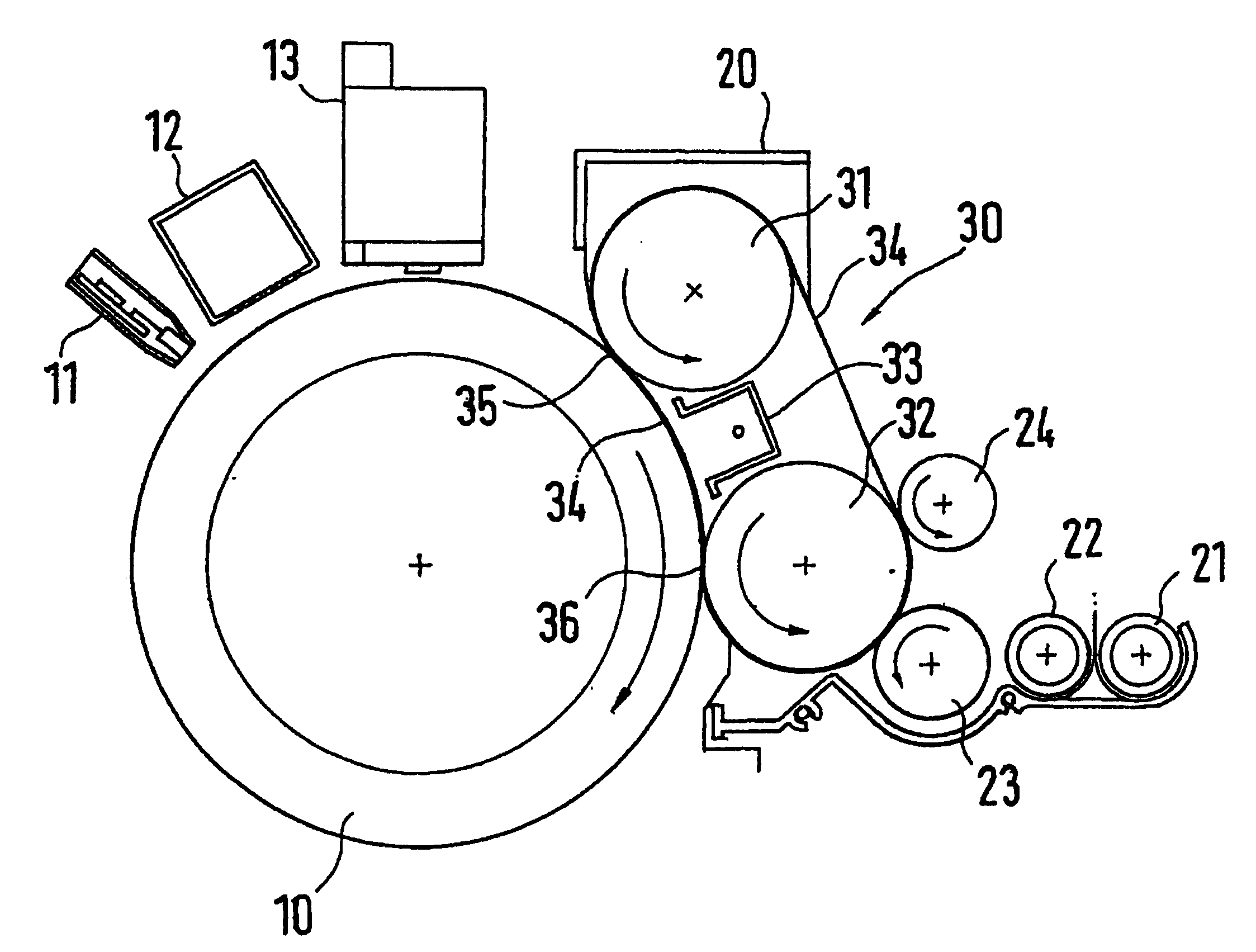
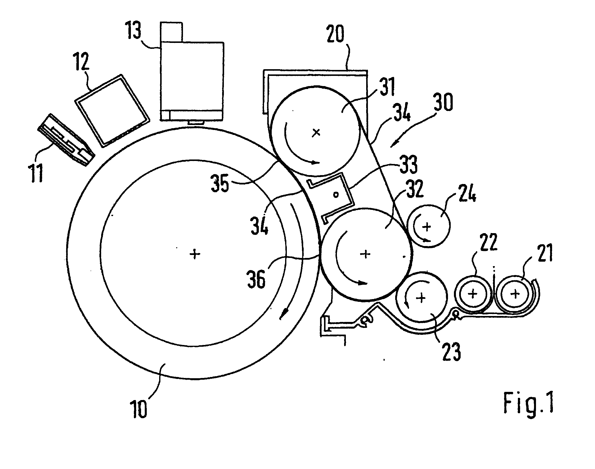
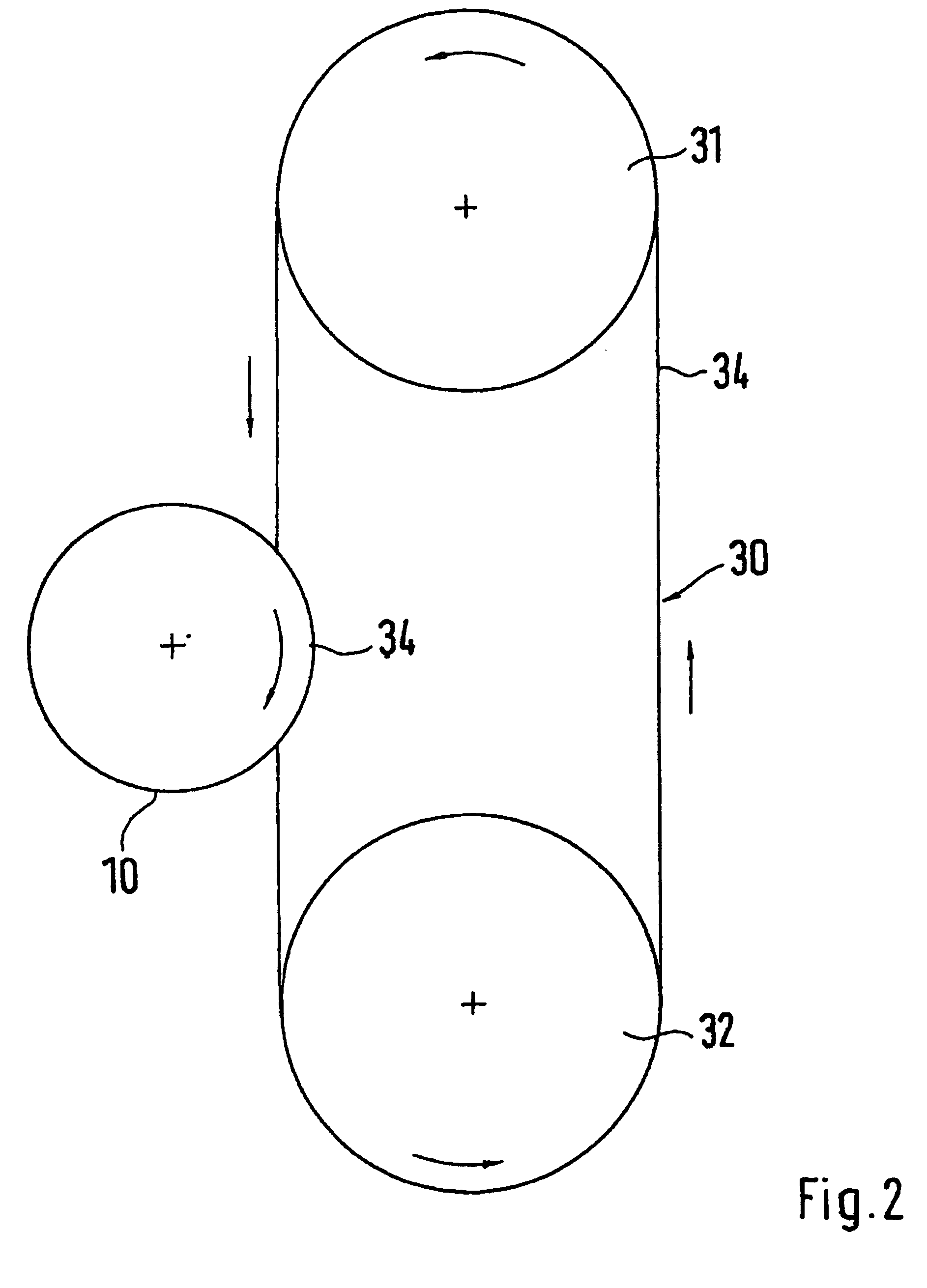
[0018] Sections of a developer unit with a developer housing 20 are represented in FIG. 1. A toner cartridge, not represented in the drawings, is assigned to the developer housing 20. Toner powder is metered from it into the area between two mixing worms 21, 22 in the developer housing. Following the mixing worms, the toner powder reaches a toner application device 23, which is designed as an application roller in the present case. The application roller 23 rolls off on the surface of a developer tape 34. The application roller 23 transfers the toner powder in the process. The developer tape 34 is guided around two deflection rollers 31, 32, which are axis-parallel with respect to each other. Viewed in the transport direction, a metering roller 24 is arranged downstream of the application roller23. It is arranged in the area of the deflection roller 32 and ensures that the surface of the developer tape 34 is always supplied with toner of a constant thickness. The deflection roller 3...


PUM


Abstract

A developer unit having a toner reservoir and a toner application device. The toner application device applies toner to a developer and the developer can be brought into a planar contact with an OPC (photo conductor drum). In order to improve the transfer of toner in the contact area between the OPC and the developer, the developer has a developer strip that is placed, in the contact area, in some areas of the surface of the OPC.

Description

BACKGROUND OF THE INVENTION [0001] 1. Field of the Invention [0002] This invention relates to a developer unit with a toner supply and a toner application device, wherein toner is applied to a developer device, and the toner can be brought into planar contact with an OPC. [0003] 2. Discussion of Related Art [0004] Such a developer unit is known from European Patent Reference EP 1 213 621 A. In this case the developer unit has an exchangeable toner supply reservoir, from which toner is metered into a developer housing. The toner is applied by an application roller to the surface of the developer roller. The developer roller rolls off on an OPC, namely a photo-conductor drum, and in the process transfers the toner material. The OPC is known and has a latent charge image. The contact area between the developer roller and the OPC is embodied in the shape of a so-called “nip”. Here, the rigid OPC surface penetrates into the elastically yielding surface of the developer roller. A planar c...

Claims


Application Information

Patent Timeline
IPC IPC(8): G03G15/08
CPCG03G15/0806G03G2215/0634G03G15/0818
Inventor SCHULTHEIS, BERND
Owner SCHOTT AG
Why Eureka
Try Eureka