
Security door/window stop

a technology for windows and doors, applied in door/window fittings, multi-purpose tools, construction, etc., can solve the problems of not being able to use suction not being able to use the cups to hold a window or door in a closed or open position, etc., to prevent the sliding of the suction cup

Inactive Publication Date: 2006-12-28
VAN VLIET GARRY
View PDF7 Cites 17 Cited by
  • Summary
  • Abstract
  • Description
  • Claims
  • Application Information

AI Technical Summary

Benefits of technology

[0021] It is an object of the present invention to provide a stop assembly that can be used on a door or a window to prevent its being opened.
[0022] It is an object of the present invention to provide a stop assembly that can be used with partially opened doors and windows to prevent their being opened further.
[0023] It is an object of the present invention to prevent the sliding of the suction cup when a lateral force is applied.
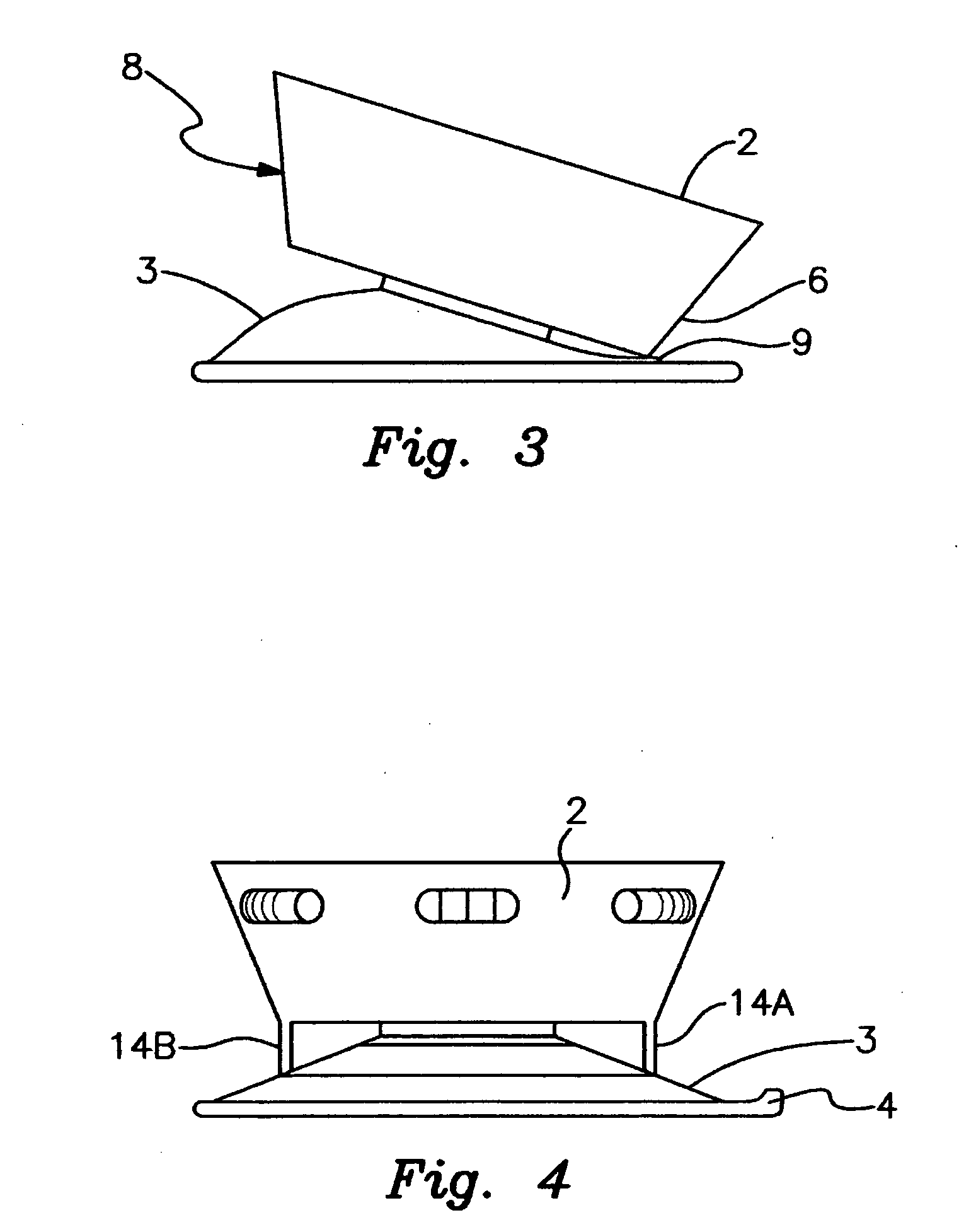
[0024] The present invention is a door stop formed of a suction cup attached to a body which is typically formed by a block of material such as clear plastic. The door stop may be used to lock sliding glass doors and windows in either a closed or in a partially open position. The suction cup will hold to the glass for up to 3 months and dual suction plugs may be used for added security. The body is designed to tip and press the suction cup down to prevent sliding and thereby hold the stop assembly in place even when a strong lateral force is applied.
[0026] The body of the stop assembly may carry a projection that is forced downward when a lateral force is applied, preventing the suction cup from sliding laterally and thereby providing a better stopping action than the suction cup alone.

Problems solved by technology

However, it fails to use suction to hold a window or door in a closed or open position.
However, it is not used to hold a window or door in a closed or open position.
However, it is not a device used to hold a window or door in a closed or open position.
However, it is not used to hold a window or door securely in a predetermined fixed open or closed position.
However, it fails to use the cups to hold a window or door in a closed or open position.
None of the above prior art patents provide a single device which can be installed quickly and function as a door or window stop or provide a decorative identification of their being a glass panel present.

Method used


Image

  • Security door/window stop
  • Security door/window stop
  • Security door/window stop

Examples


Embodiment Construction

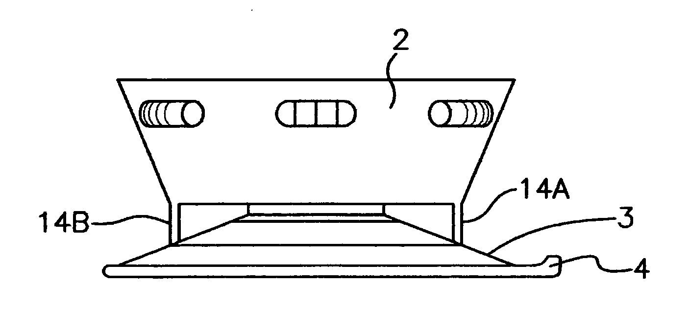
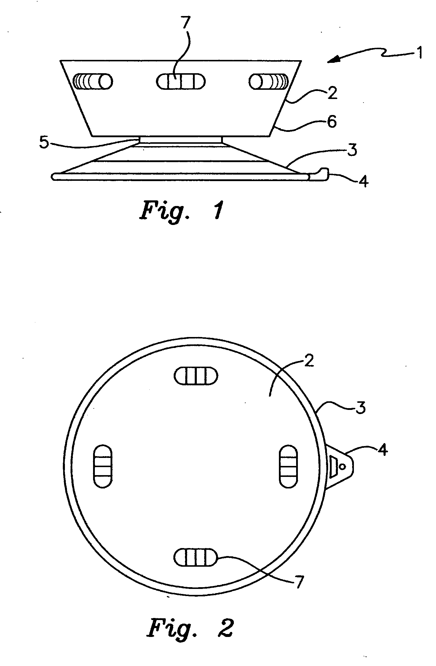
[0028]FIG. 1 is a side view of a stop assembly consisting of a body 2 and a suction cup 3. The cup has a concave shape where the outside of the raised portion in the concave shape is referred to as the pressure side and the opposite side is referred to as the suction side. The cup has a pressure side 33 and a suction side 34. The body is connected to the cup by way of a connection section 5. At the edge of the suction cup is a quick release tab 4. This tab may be lifted up which lifts up the edge of the cup to allow air into the cup dissolving suction beneath the cup and allowing the cup to be easily removed from the panel. About the lower edge of the body 6 is a corner which contacts the cup when the body is pressed laterally. In the use of the stop assembly 1, the body 2 is pressed downward on the pressure side 33, forcing air out of the suction cup 3 from the suction side 34 causing it to adhere on the suction side to whatever surface it has been placed against, typically a panel...


PUM


Abstract

A door stop formed of a suction cup attached to body, typically formed of a block of material such as clear plastic, which may be used to lock sliding glass doors and windows in either a closed or in a partially open position. The suction cup will hold to the glass for up to 3 months and dual suction plugs may be used for added security. The body is designed to tip and press the suction cup down to prevent sliding and thereby hold the stop assembly in place even when a strong horizontal force is applied. The body contains an alarm to discourage intruders in the event that the stop is dislodged from the door.

Description

BACKGROUND [0001] 1. Field [0002] The present invention relates to door stops and more particularly to such stops that employ suction cups allowing them to be installed instantly without the use of tools, especially on glass doors and windows. [0003] 2. Prior Art [0004] The following is a list of patents which are either related to door stops or suction cups or a combination of both. [0005] U.S. Pat. No. 4,084,290 illustrates a stop for limiting the upward movement of closures such as slidable windows and doors. However, it fails to use suction to hold a window or door in a closed or open position. [0006] U.S. Pat. No. 5,087,005 illustrates a suction cup assembly for securing a device to a surface. However, it is not used to hold a window or door in a closed or open position. [0007] U.S. Pat. No. 5,104,077 illustrates a suction device. However, it is not a device used to hold a window or door in a closed or open position. [0008] U.S. Pat. No. 5,288,257 illustrates an elongate flexib...

Claims


Application Information

Patent Timeline
IPC IPC(8): E05F5/02
CPCE05C17/525E05F5/003E05Y2201/224Y10T16/61E05Y2900/148E05Y2900/132E05Y2600/52
Inventor VAN VLIET, GARRY
Owner VAN VLIET GARRY
Learn More