Automatic ice maker

a technology of automatic ice making machine and ice maker, which is applied in the direction of manufacturing tools, applications, lighting and heating apparatus, etc., can solve the problems of increasing water consumption, reducing the efficiency of ice making, and prolonging the ice making operation, so as to achieve stable ice making operation and reduce the effect of ice making efficiency and reducing the effect of ice making tim

Active Publication Date: 2006-12-28
HOSHIZAKI ELECTRIC CO LTD
View PDF5 Cites 46 Cited by
  • Summary
  • Abstract
  • Description
  • Claims
  • Application Information

AI Technical Summary

Benefits of technology

[0017] According to an automatic ice making machine of the present invention, since a metal plate, an insulating layer and each of heating means are laminated by thermocompression bonding without using an adhesive, adhesive degeneration caused by generating heat in the heating means by applying current does not separate the metal plate, the insulating layer and the heating means from each other, thereby cooling the heating means reliably so as to perform a stable ice making operation. Therefore, the heating means can be cooled efficiently during the ice making operation, thereby producing no decrease in ice making efficiency.
[0018] Also, according to another automatic ice making machine of the invention of the present application, since a metal plate, an insulating layer and each of heating means are laminated and the external outline of the heating means is located inside the external outline of the insulating layer, the metal plate and the heating means can be reliably prevented from making contact with each other. Therefore, the metal plate can be insulated from the heating means reliably thereby preventing a decrease in heat generation efficiency of the heating means when applying current through the heating means.

Problems solved by technology

As described above, in the automatic ice making machine which uses both hot gas and deicing water during the deicing operation, the deicing operation becomes longer and the ice making capacity per unit time has limitations.
Also, use of deicing water results in increase in water consumption, thereby requiring a higher running cost.
According to this configuration, the deicing operation becomes shorter and deicing water becomes unnecessary.

Method used


Image

  • Automatic ice maker
  • Automatic ice maker
  • Automatic ice maker

Examples


modification example

[Modification Example]

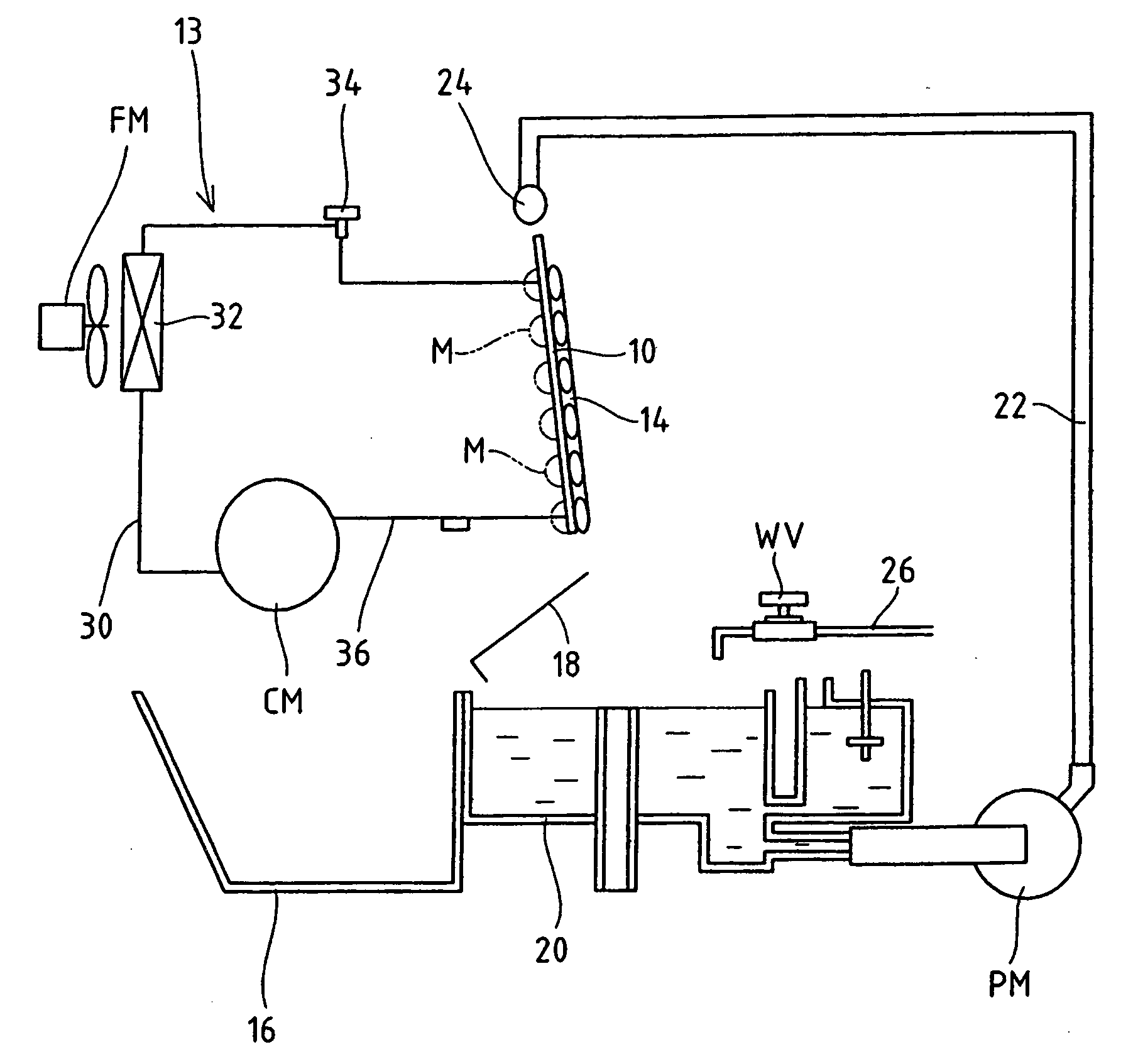
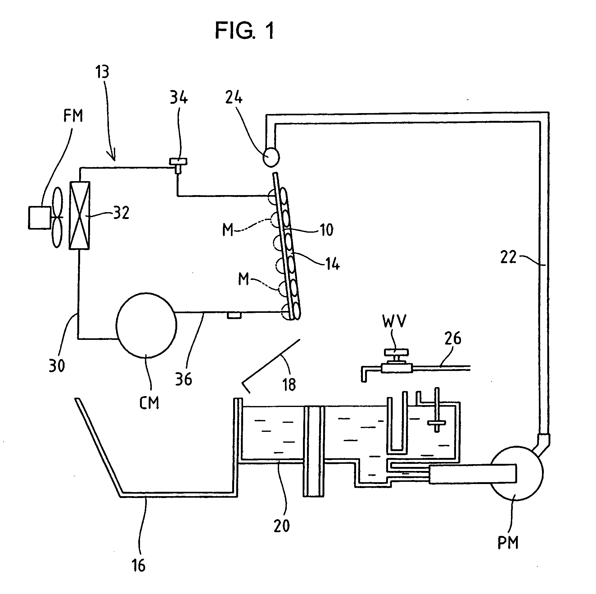
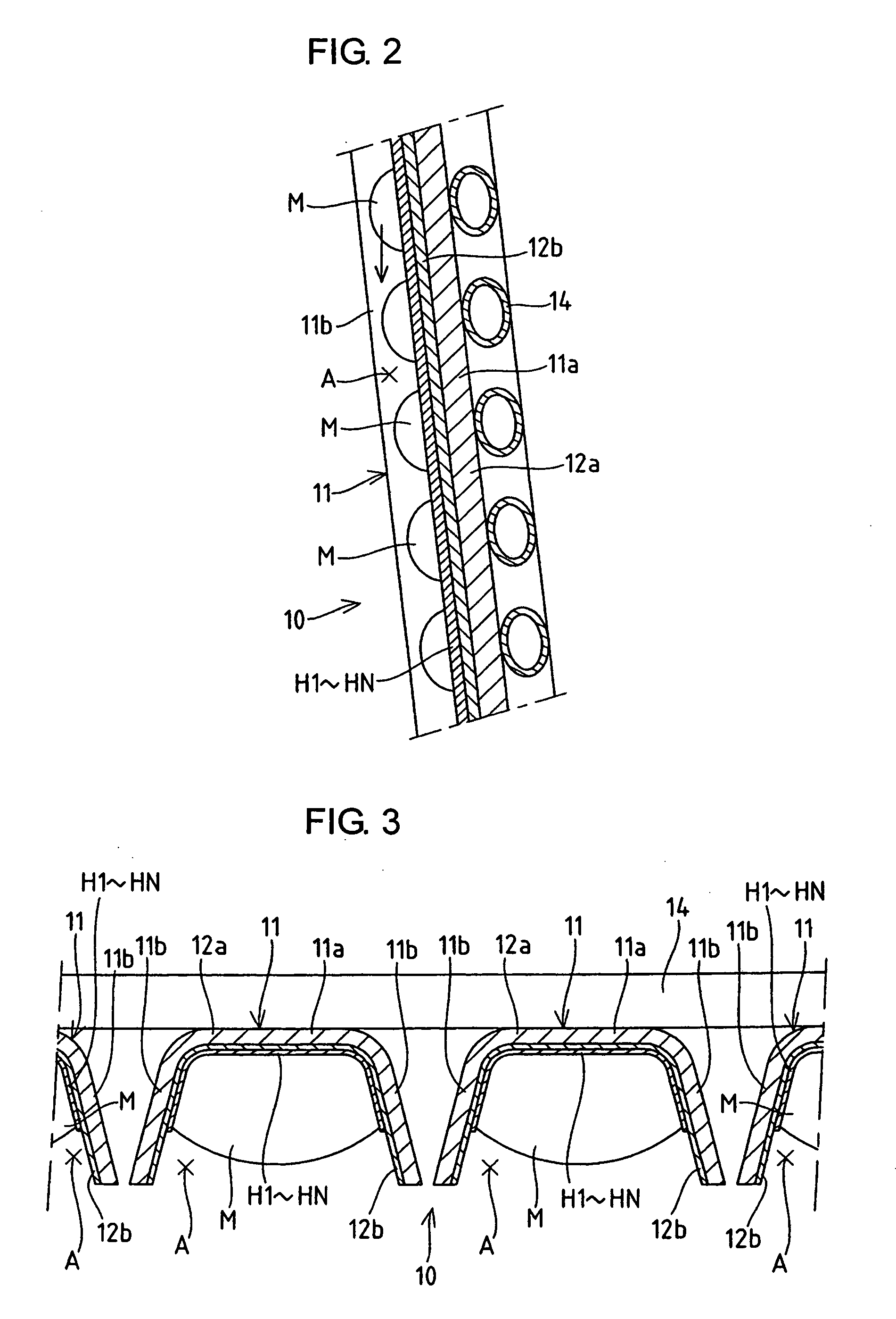
[0045] It should be noted that the automatic ice making machine according to the present invention is not limited to that in the Example described above, but various modifications are applicable. For example, the Example is configured so that an ice block is removed from a single ice making member and another ice block is then removed from a next ice making member. However, with a plurality of ice making members as one unit of ice making area, an ice block can be removed by the unit. Also, although the heating means provided for each ice making area is individually controlled for applying current and stopping current application in the Example, by controlling applying current and stopping current application over the heating means on a given group basis, the ice block in the ice making area corresponding to the heating means through which current application is controlled can also be removed by melting. Subsequently, although the ice making section is composed ...


PUM

PropertyMeasurementUnit
thicknessaaaaaaaaaa
thicknessaaaaaaaaaa
thicknessaaaaaaaaaa

Abstract

The peel off between an ice making plate and an insulating layer or between the insulating layer and heating means is prevented so that an ice making operation can be performed efficiently. Also, a metal plate is insulated from the heating means reliably. An evaporation pipe 14 and electric heaters H1 to HN are provided in an ice making member 11. A coolant is circulatingly supplied through the evaporation pipe 14 so as to cool the ice making member 11 and ice making water is supplied to the ice making member 11 so as to form an ice block M during the ice making operation. During the deicing operation, heat is generated in the heaters H1 to HN by applying current so that the ice block M is removed from the ice making member 11 by melting. The ice making member 11, in a state that an insulating layer 12b lies between a metal plate 12a to which the evaporation pipe 14 is fixed and the heaters H1 to HN, is formed by bonding the metal plate 12a with the insulating layer 12b, and the insulating layer 12b with each of the heaters H1 to HN by thermocompression. Also, in addition to thermocompression bonding, the external outline of the heating means (H1 to HN) may be located inside the insulating layer 12b.

Description

TECHNICAL FIELD [0001] The present invention relates to an automatic ice making machine which generates heat in heating means by applying current so as to remove an ice block formed in an ice making section. BACKGROUND ART [0002] An automatic ice making machine for making large volume of ice blocks automatically in which an evaporation pipe is provided in an ice making section led out from a refrigeration system having a compressor, a condenser and the like, is configured so as to form an ice block by supplying ice making water to the ice making section cooled by a coolant supplied circulatingly through the evaporation pipe, thereby dropping and releasing the obtained ice block by separation. The automatic ice making machine, which has an ice making water tank for retaining a required amount of ice making water, is configured so that ice making water in the tank is fed by pressure by a circulating pump to be supplied to the ice making section during the ice making operation, and tha...

Claims


Application Information

Patent Timeline
Patent Type & Authority Applications(United States)
IPC IPC(8): F25C5/08F25C1/00F25C1/22
CPCF25C5/08F25C1/22
Inventor MORI, KAZUHIROHIRANO, AKIHIKO
Owner HOSHIZAKI ELECTRIC CO LTD
Why Eureka
Try Eureka