Internal combustion engine start-up control

a technology of internal combustion engine and start-up control, which is applied in the direction of electric control, machines/engines, instruments, etc., can solve the problems of promoting valve overlap, reducing the lift amount of the intake valve, and reducing the wall flow amount.

Active Publication Date: 2006-12-28
NISSAN MOTOR CO LTD
View PDF4 Cites 10 Cited by
  • Summary
  • Abstract
  • Description
  • Claims
  • Application Information

AI Technical Summary

Benefits of technology

[0011] Another known technique to decrease wall flow amount during engine start-up other than decreasing the lift amount of the intake valve as in the prior art is to promote a valve overlap between the intake valve and the exhaust valve.

Problems solved by technology

On the other hand, when the temperature of the intake valve and the walls of the intake port has risen to a certain level, the absolute amount of wall flow is small and the effect of the prior art technique is also small.
As a result, the effect of promoting valve overlap surpasses the effect of the prior art technique at a certain time point from the engine start.

Method used


Image

  • Internal combustion engine start-up control
  • Internal combustion engine start-up control
  • Internal combustion engine start-up control

Examples


Embodiment Construction

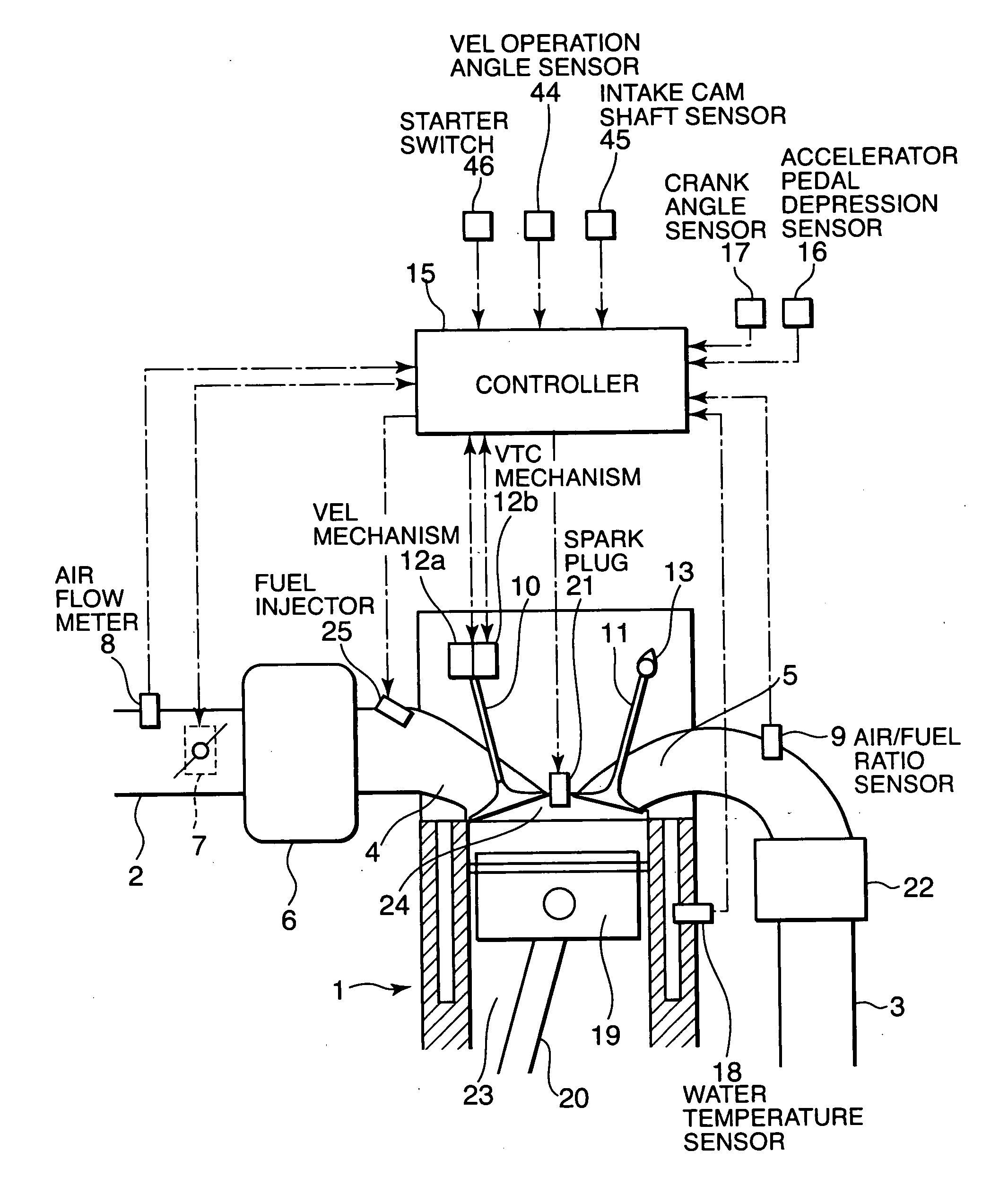
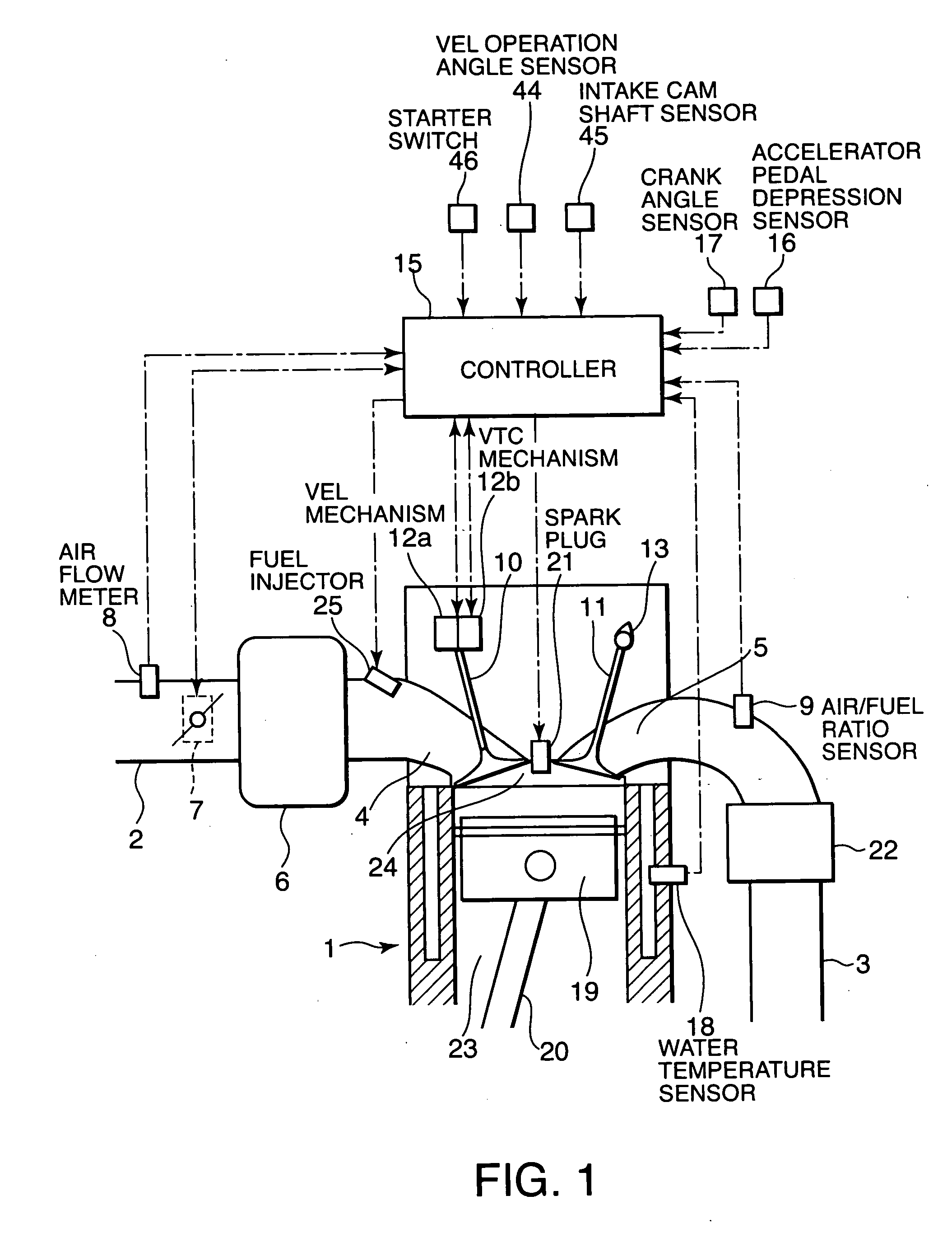
[0032] Referring to FIG. 1 of the drawings, a spark ignition multi-cylinder internal combustion engine 1 for a vehicle comprises an intake port 4 and an exhaust port 5 facing a combustion chamber 24 of each cylinder 23. The intake ports 4 are connected to an intake passage 2 via an intake collector 6. The exhaust ports 5 are connected to an exhaust passage 3 via a merge collector.

[0033] An electronic throttle 7 which regulates an intake air amount of the engine 1 in response mainly to a depression amount of an accelerator pedal with which the vehicle is provided is disposed in the intake passage 2. The intake air regulated by the electronic throttle 7 is temporarily stored in the collector 6 and then supplied to the intake port 4 of each cylinder 23. A fuel injector 25 is installed in the intake port 4.

[0034] The engine 1 further comprises a spark plug 21 facing the combustion chamber 24 and a piston 19 housed in the cylinder 23. The piston 19 is connected to a crank shaft via a c...


PUM


Abstract

A variable valve mechanism (12a, 12b) varies a lift amount and an opening/closing timing of an intake valve (10) of an internal combustion engine (1). During a first period in an engine start operation, wall flow is suppressed by setting the lift amount of the intake valve (10) to be smaller so as to increase the intake air velocity. During a second period, which starts after the first period ends, the atomization of injected fuel is enhanced by increasing a valve overlap amount between the intake valve (10) and an exhaust valve (11) so as to promote blow-back of the combustion gas to an intake port (4). By sequentially applying a process for increasing the intake air velocity and a process for increasing the valve overlap amount, the emission of unburned hydrocarbon during the engine start is effectively reduced.

Description

FIELD OF THE INVENTION [0001] This invention relates to start-up control of an engine provided with a variable valve mechanism. BACKGROUND OF THE INVENTION [0002] During a cold start of an internal combustion engine, or in a period immediately after the cold start thereof, the temperature of intake valves and that of the walls of the intake ports are low, and fuel adhered to these parts is not likely to atomize. As a result, the amount of fuel flowing into the combustion chamber is small with respect to the amount of fuel injected from the fuel injectors. [0003] The fuel adhered to the intake valves or the walls of the intake ports forms so called a wall flow. It is known that the wall flow flows into the combustion chamber at a delay with respect to the flow of fuel which is directly aspirated into the combustion chamber in the form of mist or vapor. [0004] During the engine start and a period immediately after the engine start, the fuel injection amount is generally increased to c...

Claims


Application Information

Patent Timeline
Patent Type & Authority Applications(United States)
IPC IPC(8): F02D43/00F02D41/06
CPCF01L1/022Y02T10/18F01L13/0026F01L2001/34469F01L2013/0073F01L2800/00F01L2820/032F02D13/0261F02D41/0002F02D41/006F02D41/064F02D41/08F02D2041/001Y02T10/42F01L1/3442Y02T10/12Y02T10/40
Inventor WATANABE, SATOSHISATOU, RITSUO
Owner NISSAN MOTOR CO LTD
Why Eureka
Try Eureka