
Methods and apparatus for user interaction with RFID cards

a technology of user interaction and rfid card, which is applied in the field of methods and apparatus for user interaction with rfid cards, can solve the problems of significant problems and limitations of such feedback methods, and the inability to hear the beep of the user, and the difficulty of visible light feedback methods,

Inactive Publication Date: 2006-12-28
OUTLAND RES
View PDF0 Cites 108 Cited by
  • Summary
  • Abstract
  • Description
  • Claims
  • Application Information

AI Technical Summary

Benefits of technology

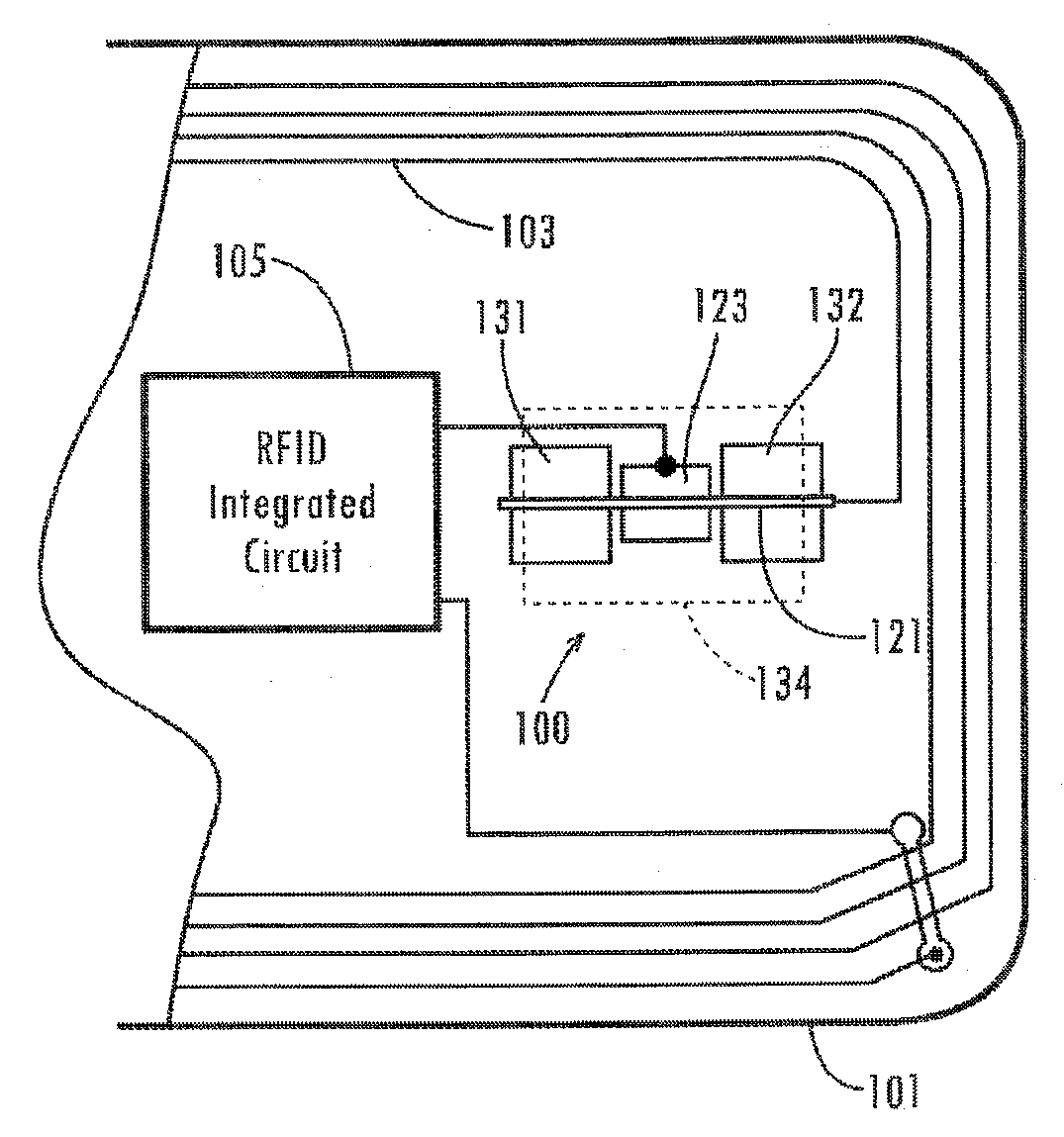
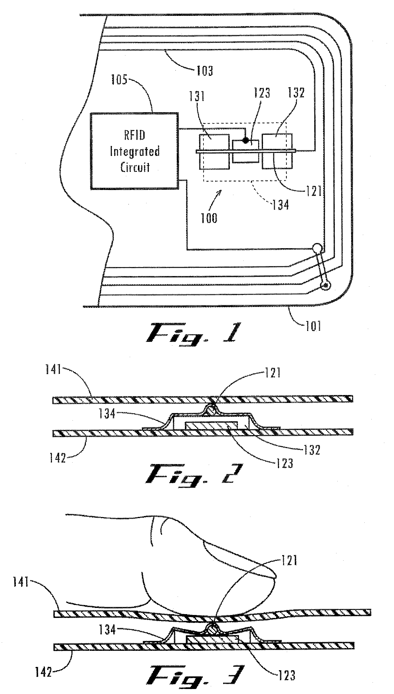
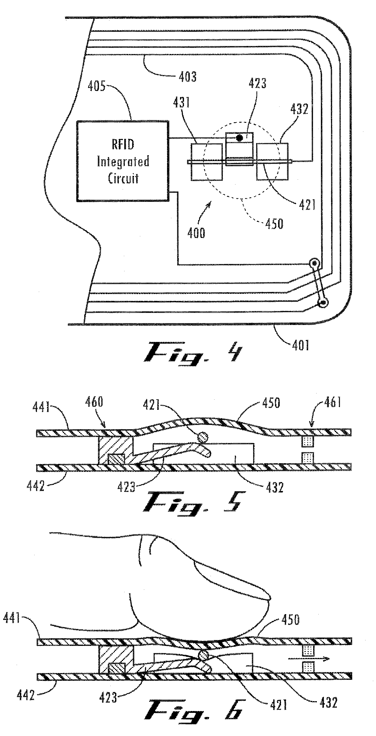
[0010] One exemplary embodiment disclosed herein provides a radio operated data card that includes a housing, an antenna coupled to the housing, electronic circuitry coupled to the antenna, control electronics adapted to generate a control signal when at least one predetermined event has occurred between the electronic circuitry and the card reader, and a tactile sensation generator coupled to the housing and connected to the electronic circuitry. The housing is adapted to be contacted by a user and includes first and second panels that form an outer surface of the housing. Moreover, the antenna, the electronic circuitry, and the control electronics are sandwiched between the first and second panels. The electronic circuitry includes a data memory and a transceiver for transferring data between the memory and a card reader via the antenna. The tactile sensation generator is configured to generate a tactile sensation corresponding to the control signal. Accordingly, the tactile sensation is adapted to be felt by a user via the housing to thereby inform the user of the occurrence of the at least one predetermined event.
[0011] Another exemplary embodiment disclosed herein provides non-contact storage device that includes a housing, an antenna coupled to the housing, electronic circuitry coupled to the antenna, control electronics adapted to generate a control signal corresponding to the status of a transfer of data between the data memory and the remote unit, and a tactile sensation generator coupled to the housing and connected to the electronic circuitry. The housing adapted to be contacted by a user. The electronic circuitry includes a data memory and a transceiver for transferring data between the memory and a remote unit via the antenna. The tactile sensation generator is configured to generate a tactile sensation corresponding to the control signal. A

Problems solved by technology

There are significant problems and limitations of such feedback methods.
First, the audible beep is not always discernable by a user because the environment of the card reader may be too noisy and the audible beep may not be heard.
The visible light feedback method also has problems.
For example, light emitted by an LED is not easily visible in bright outdoor environments.
In addition, the visible light requires the user to focus his or her visible attention on the card reader hardware, taking his or her attention away from other things he or she may be doing, thereby reducing some of the inherent convenience associated with use of RFID card systems.
Further, feedback such as visible light and audible beeps are problematic in that they are not private to a particular user.
For example, a visible light flash and / or audible beep that signals a credit-card denial can be embarrassing for the customer to whom it is intended.
Although such a switch gives the user control over the accessibility of a card by one or more non-contact readers, the current state of the art has no way to provide feedback to the user as to whether or not his or her card was successfully accessed by the non-contact reader.
For example, the user may press the switch, enabling his or her card to be accessed by a reader, but the card may not be within sufficient proximity of the reader at the time the press was performed and hence the desired data exchange may not occur.
Similarly, the current state of the art has no way for a card to give a user feedback as to whether a desired non-contact data exchange was successfully completed between the card and the reader.

Method used


Image

  • Methods and apparatus for user interaction with RFID cards
  • Methods and apparatus for user interaction with RFID cards
  • Methods and apparatus for user interaction with RFID cards

Examples


Embodiment Construction

[0023] The following description is not to be taken in a limiting sense, but is made merely for the purpose of describing the general principles of exemplary embodiments. The scope of the embodiments disclosed below should be determined with reference to the claims.

[0024] Numerous embodiments of the present invention are adapted to provide electronically-controllable tactile feedback to a user via a non-contact information storage device (e.g., an RF-enabled card), wherein the electronically controlled tactile feedback is imparted by a tactile sensation generator under electronic control to the user of the card based upon the occurrence of predetermined events (successful and / or unsuccessful) relevant to the RFID card.

[0025] RF-enabled cards, identification tags, payment cards, and the like (herein referred to as “cards” or “data cards”) carry data which typically identifies and relates to a specific person, a particular account, an individual vehicle, or an item, and further cont...


PUM


Abstract

A non-contact storage device includes a housing, an antenna coupled to the housing, electronic circuitry coupled to the antenna, control electronics adapted to generate a control signal when at least one predetermined event has occurred between the electronic circuitry and the card reader, and a tactile sensation generator coupled to the housing and connected to the electronic circuitry. The housing is adapted to be contacted by a user. The electronic circuitry includes a data memory and a transceiver for transferring data between the memory and a card reader via the antenna. The tactile sensation generator is configured to generate a tactile sensation corresponding to the control signal. Accordingly, the tactile sensation is adapted to be felt by a user via the housing to thereby inform the user of the occurrence of the at least one predetermined event.

Description

[0001] This application claims the benefit of U.S. Provisional Application No. 60 / 693,642, filed Jun. 25, 2005, which is incorporated in its entirety herein by reference.BACKGROUND [0002] 1. Field of Invention [0003] Embodiments disclosed herein relate generally methods and apparatus facilitating user interaction with non-contact data storage devices, and more specifically to methods and apparatus for providing users with enhanced interaction with and feedback from RFID cards. [0004] 2. Discussion of the Related Art [0005] Presently, non-contact cards are being developed as a means of enabling a user to interface to a remote electronic device and exchange data with the remote electronic device by simply bringing a card within a certain proximity of an external radio transceiver. Such non-contact cards typically constitute a radio operated data card (i.e., an RFID card) including an RFID integrated circuit which incorporates data storage means, a radio frequency transceiver, and an o...

Claims


Application Information

Patent Timeline
IPC IPC(8): G06K19/06
CPCG06K19/07345H01H2239/076H01H2231/05
Inventor ROSENBERG, LOUIS B.
Owner OUTLAND RES
Learn More