

Driver-assistance vehicle
- Summary
- Abstract
- Description
- Claims
- Application Information
AI Technical Summary
Benefits of technology
Problems solved by technology
Method used
Image

Examples
first embodiment
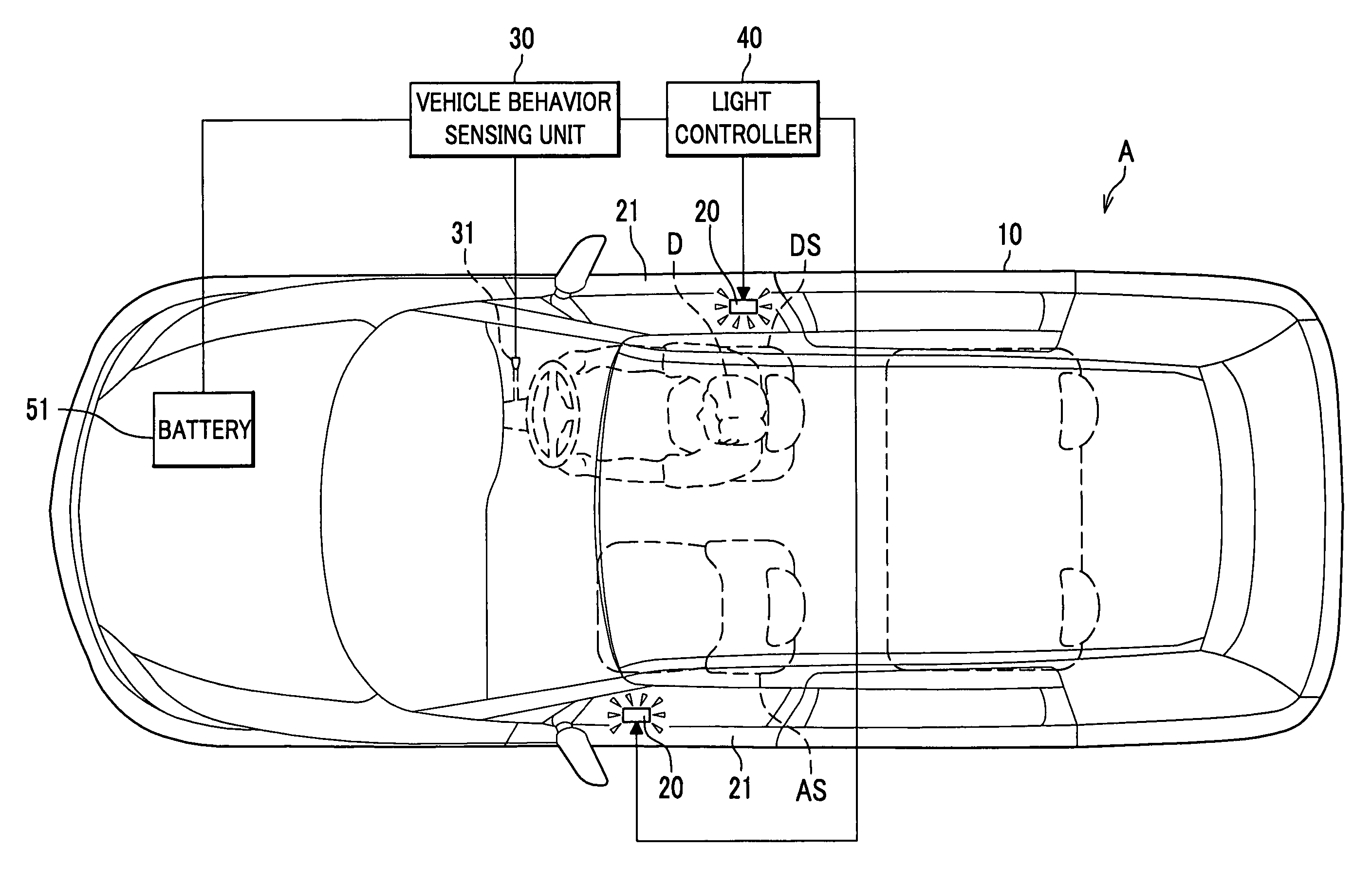
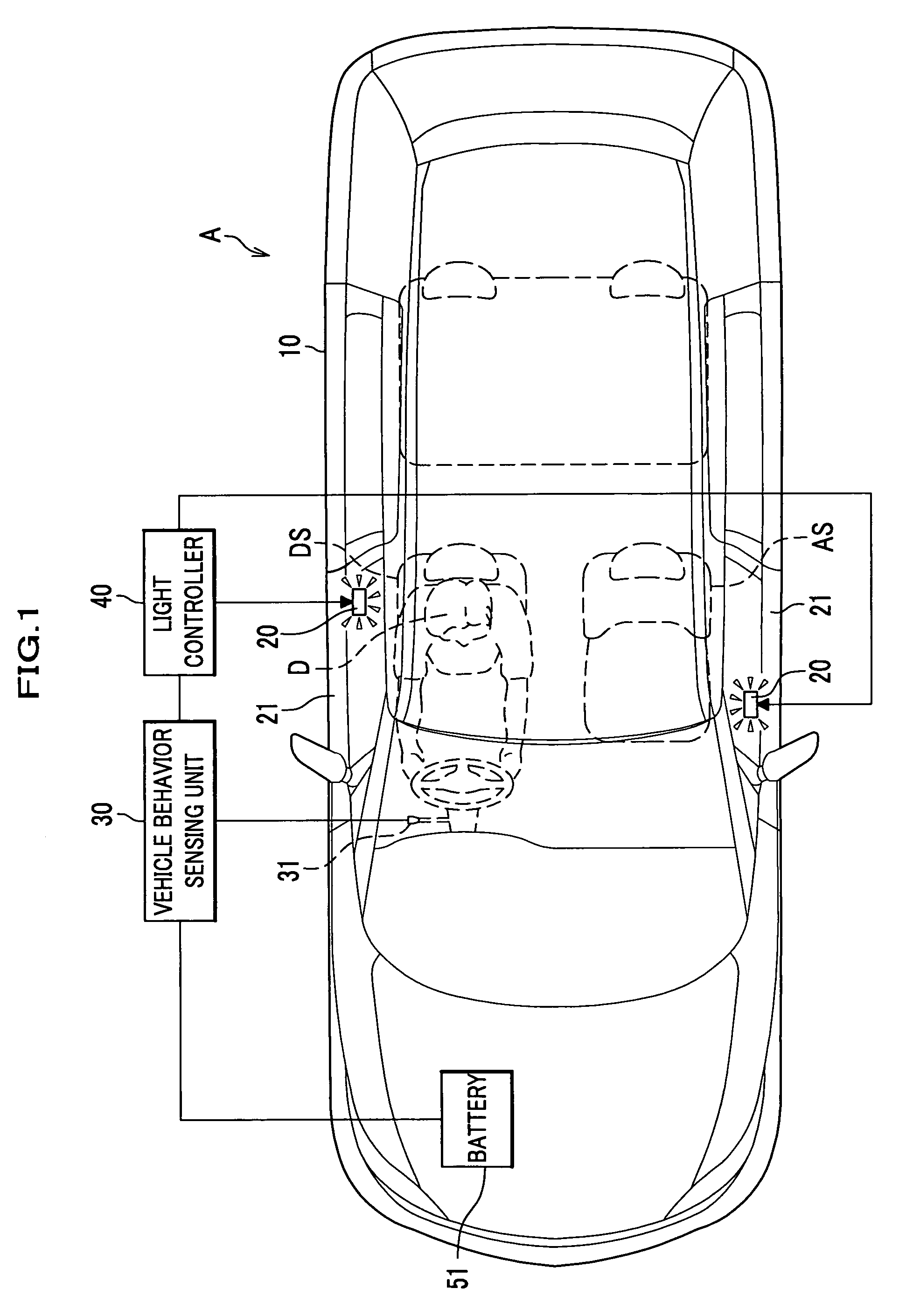
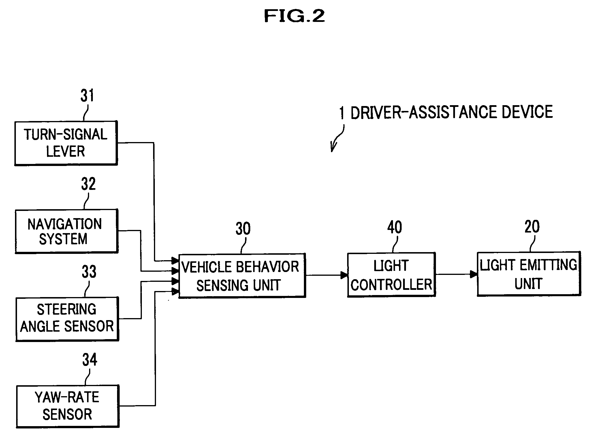
[0037] Referring to FIGS. 1 and 2, a driver-assistance vehicle A is equipped with a driver-assistance device 1. In addition, the driver-assistance device 1 includes a vehicle 10, a pair of light emitting units 20 and 20 arranged on the respective sides of the vehicle 10, a vehicle behavior sensing unit 30 for sensing the state of the vehicle 10, and a light controller 40 for controlling the light emitting units 20 and 20.
[0038] The vehicle 10 may be a typical vehicle, and it may be of any type as long as containing a passenger space. The vehicle 10 includes a battery 51 which supplies electric power to the driver-assistance device 1 (see FIG. 2).
[0039] Each light emitting unit 20 may be a light emitting diode (LED), incandescent lamp or fluorescent light, and both units 20 and 20 are arranged below the windows on the front doors 21 and 21, respectively, as shown in FIGS. 3A and 3B. In these embodiments, front, back, right and left directions correspond to those seen from a driver ...
second embodiment
[0054] Now, a description will be given below, of a driver-assistance device according to a second embodiment of the present invention. A driver-assistance device of a second embodiment includes two light emitting units on the front door 21 of the assistant driver's seat. The two light emitting units are switched depending on whether or not a passenger exists on the assistant driver's seat AS. The driver-assistance device of the second embodiment is similar to that of the first embodiment. Therefore, the same reference numerals are given to the same parts as those already described in the first embodiment, and duplicate description is omitted.
[0055] Referring to FIG. 6, a driver-assistance vehicle B has two light emitting units 20 and 20 on the front door 21 of the assistant driver's seat AS. One of the light emitting units (called a “light emitting unit 20R”) is placed just beside the head of the driver D, similar to the light emitting unit 20 on the side of the driver D. The othe...
third embodiment
[0064] Next, a description will be given below, of a drive-assistance vehicle C according to a third embodiment of the present invention. In this embodiment, the light intensity of the light emitting units is varied in accordance with external darkness.
[0065] Referring to FIG. 8, the structure of a driver-assistance device 1′ is similar to that of the driver-assistance device 1 of the first embodiment except for an illuminance meter 36 and a light control switch 37.
[0066] The illuminance meter 36 is set on a dashboard of the vehicle 10, and senses illuminance thereon. The sensed value is outputted to the vehicle behavior sensing unit 30′. The light control switch 37 is used to turn on headlights and fog lamps or to vary the light intensity of the light emitting units. Generally, when it is dark outside, the headlights or the fog lamps are turned on. Therefore, in order to sense the illuminance outside the vehicle 10, the ON / OFF of the light control switch 37 may be detected, inste...
PUM
 Abstract
Description
Claims
Application Information