Blind-spot detection system for vehicle

a blind spot detection and vehicle technology, applied in traffic control systems, transportation and packaging, instruments, etc., can solve the problems of inability to detect the occurrence of a failure in the obstacle indicator, the difficulty of the driver to check simultaneously the display and the failure warning unit, and the inability of the driver to reliably ensur

Active Publication Date: 2006-12-28
MAZDA MOTOR CORP
View PDF7 Cites 73 Cited by
  • Summary
  • Abstract
  • Description
  • Claims
  • Application Information

AI Technical Summary

Benefits of technology

[0008] In the above blind-spot detection system for vehicle of the present invention, the warning means in the side mirror is visually recognized simultaneously by a passenger when the passenger, particularly the driver of the vehicle visually checks the display mea

Problems solved by technology

This layout makes it difficult for a driver to check simultaneously the display and the failure warning unit.
Therefore, in the conventional BSD system, the difficulty for driver is inevitable in reliably make sure whether or not the obstacle indicator is in a failed state when the driver is watching the display on the door mirror.
Moreover, it is qui

Method used


Image

  • Blind-spot detection system for vehicle
  • Blind-spot detection system for vehicle
  • Blind-spot detection system for vehicle

Examples


first embodiment

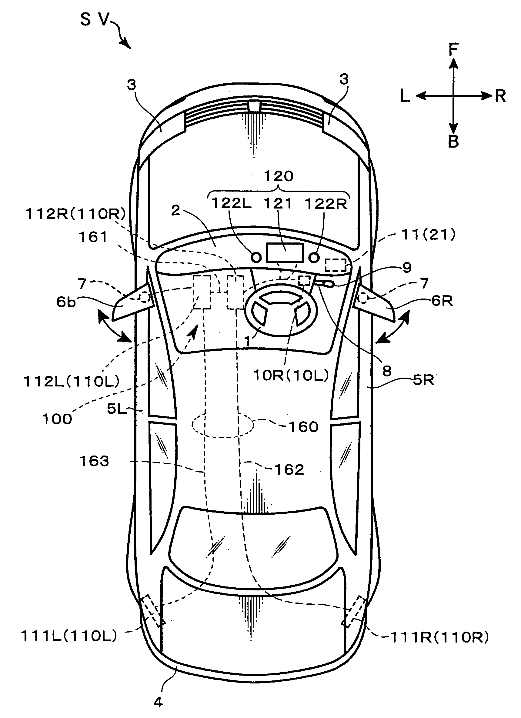
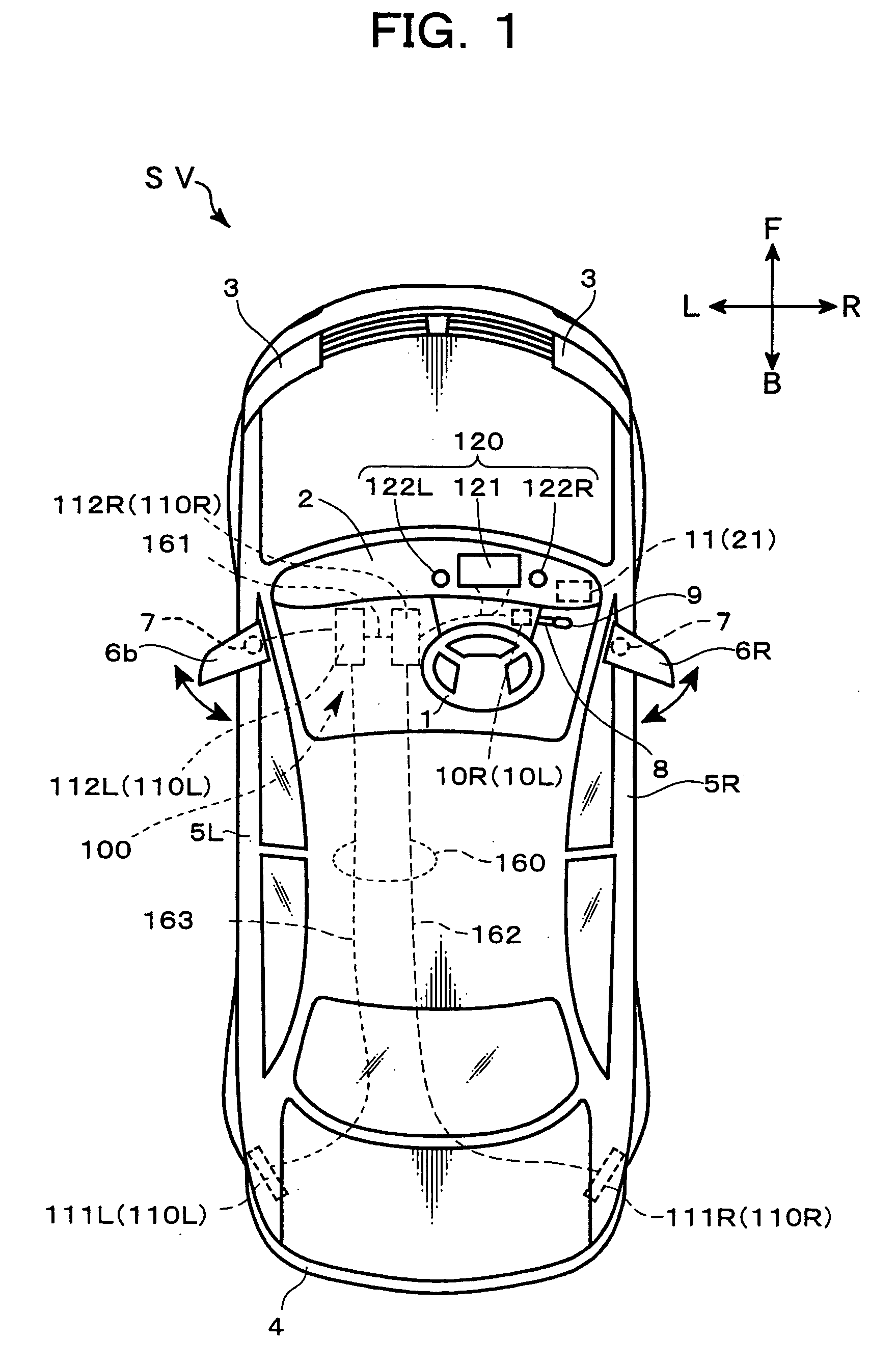
[0078] With a view to embodying the above BSD system 100, a pair of left and right side mirrors or door mirrors 6 arranged in a symmetric manner are employed in a first embodiment of the present invention. Therefore, the subscripts “L” and “R” indicating “left” and “right” will be omitted in the following description.

[0079] Referring to FIGS. 7 and 8, the door mirror 6 is a unit body which is provided with a frame 61 disposed on the body of the vehicle SV, a mirror glass 62 mounted on the frame 6, a heater 63 disposed on the side of a back surface of the mirror glass 62 and housed in the frame 61, and a cover 64 fixing the mirror glass 62 and the heater 63 to the frame 61.

[0080] The frame 61 is a supporting structure for the mirror glass 62 and the heater 63, and formed with an engagement portion 66 engageable with the door-mirror drive unit 7. Through this engagement portion 66, the door mirror 6 as a unit body is driven by the door-mirror drive unit 7 in such a manner as to be m...

second embodiment

[0121] As shown in FIG. 15, in a BSD system according to a second embodiment of the present invention, when it is determined that the left and right door mirrors 6 are not in the deployed position, based on an output of the door-mirror deploying switch 22 (“NO” in Step S504), the door mirror control element 1129 controls the door mirror drive unit 7 to move the door mirrors 6 to the deploy position, in Step S505. Preferably, in Step 505 illustrated in FIG. 15, the movements of the left and right door mirrors 6 to the deploy position are controllably initiated after confirming safe conditions that no obstacle exists around the vehicle SV, using a corner sensor mounted on the vehicle SV.

[0122] In the second embodiment, the door mirrors 6 are automatically deployed when the ignition switch 21 is turned ON, provided that the rearward obstacle alert system is demanded to be activated. Thus, regardless the operation of the main switch 101 of the BSD modules 110, it can be checked whether...

third embodiment

[0123] As shown in FIG. 16, in a BSD system according to a third embodiment of the present invention, a given condition (timing condition) is set to the warning based on warning means in the failure indication subroutine S5. In this embodiment, the failure-warning determination element 1126 controls the in-cabin warning LED 122 to indicate a warning when an elapsed time T1 after initiation of the ON state of the ignition switch 21 falls within a given time Tc1. Further, the failure-warning determination element 1126 controls the in-mirror warning LED 142 to indicate a warning when the main switch 101 turns ON and before a given time elapses after the vehicle speed becomes equal to or greater than 10 km / h.

[0124] When the failure flag F is set at “n” through the operation in Step S4, the failure-warning determination element 1126 determines whether or not the elapsed time T1 after initiation of the ON state of the ignition switch 21 is equal to or less than the given time Tc1 (Step S...


PUM


Abstract

Disclosed is a BSD system for vehicle provided with a blind spot detection module which includes obstacle in blind spot detection means for detecting an obstacle existing in a blind spot around the rear side of a self vehicle and an obstacle indicator disposed on a side mirror of the self vehicle and adapted to display at least one of information for the existence of an obstacle in the blind spot, for a distance between the obstacle and the self vehicle, and for a relative speed of the obstacle to the self vehicle, the blind-spot detection system for vehicle. This system is provided with means for detecting that the blind spot detection module is in an abnormal operation state and means disposed on the side mirror having the obstacle indicator and adapted to visually indicate an abnormality of the blind spot detection module detected by the abnormality detection means.

Description

BACKGROUND OF THE INVENTION [0001] 1. Field of the Invention [0002] The present invention relates to a blind-spot detection (BSD) system for vehicle having an obstacle indicator for displaying information relevant to an obstacle existing in a blind spot around a vehicle driver. [0003] 2. Description of the Related Art [0004] Heretofore, there has been known a vehicle equipped with a BSD system for supporting vehicle safety-driving. For example, US Patent Application No. 2002 / 281880 discloses a distance measuring and display system designed to indicate a distance between a driver's vehicle or self vehicle and obstacles, and a direction toward the obstacles, on a side view mirror or a rearview mirror. [0005] In the conventional BSD system alarms the obstacle's existence in the blind corner for the driver such as rear side zone in response to operations of a turn-indicator lever or a steering wheel in case the driver intends to change the direction toward which the driver's vehicle clo...

Claims


Application Information

Patent Timeline
IPC IPC(8): B60Q1/00
CPCB60Q1/2665B60Q1/525B60Q9/008B60R1/00B60R1/12B60R2001/1253G08G1/16B60R2300/30B60R2300/301B60R2300/302B60R2300/802B60R2300/8066B60R2300/8093B60R2300/105G08G1/165G08G1/166G08G1/167
Inventor MATSUMOTO, SEIJISETO, TAKAYUKINOBUTOKI, YOSHIKAZUSATO, TAKAYUKIISOMOTO, KAZUNORIENNO, YASUHIRO
Owner MAZDA MOTOR CORP
Why Eureka
Try Eureka