Method and apparatus for transporting ethernet and radio frequency signals in fiber-optic system

a fiber-optic system and radio frequency signal technology, applied in the direction of electrical equipment, radio-over-fiber, fiber transmission, etc., can solve the problems of high cost or low complicated fiber-optic communications, etc., and achieve the effect of simple and inexpensive structure and high bit rate of digital signals

Inactive Publication Date: 2006-12-28
NAT CENT UNIV
View PDF11 Cites 27 Cited by
  • Summary
  • Abstract
  • Description
  • Claims
  • Application Information

AI Technical Summary

Benefits of technology

[0011] An advantage of the system according to the present invention is that it renders a high bit rate of digital signals possibl

Problems solved by technology

However, the conventional solutions involve complicated fiber-opt

Method used


Image

  • Method and apparatus for transporting ethernet and radio frequency signals in fiber-optic system
  • Method and apparatus for transporting ethernet and radio frequency signals in fiber-optic system
  • Method and apparatus for transporting ethernet and radio frequency signals in fiber-optic system

Examples


Embodiment Construction

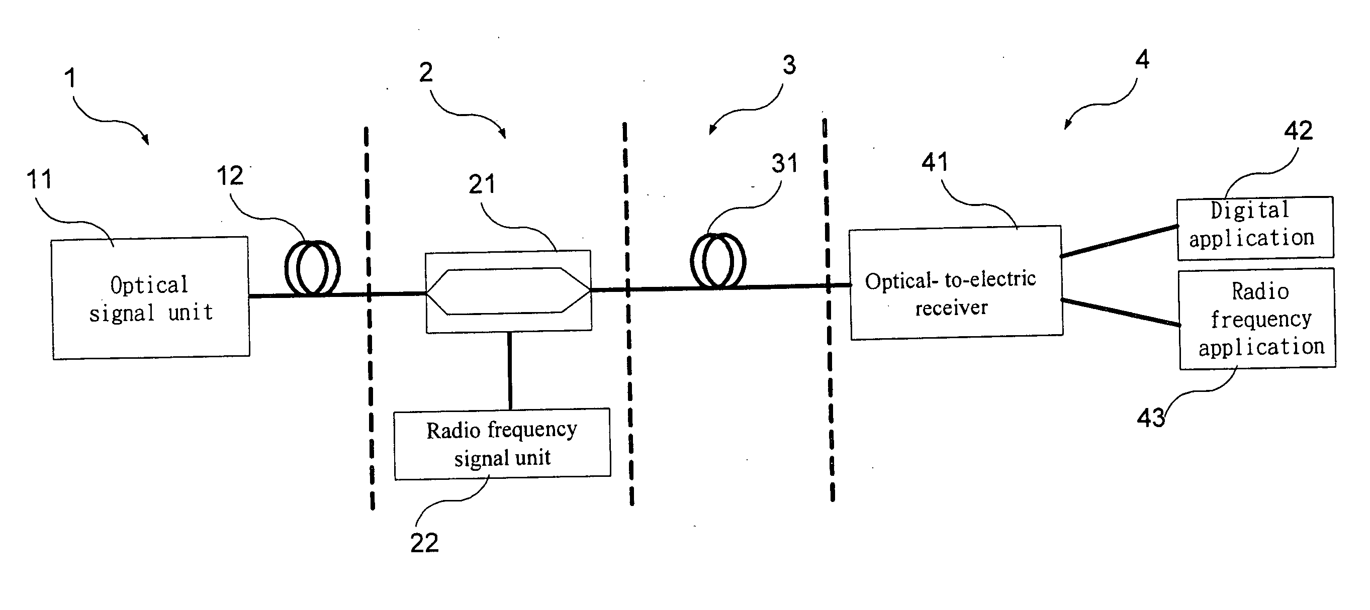
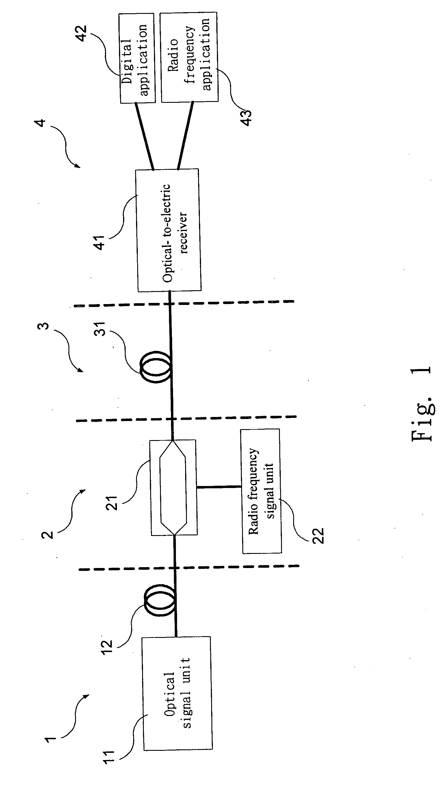
[0023] Referring to FIG. 1, there is shown a single-wavelength fiber-optic communication system that mixes an Ethernet signal with a radio frequency signal according to the preferred embodiment of the present invention. The system includes an optical Ethernet signal module 1, a mixer module 2, a transmitter module 3, and a receiver module 4. From the optical Ethernet signal module 1, an Ethernet signal in an optical form is transmitted to an optical input of the mixer module 2. A radio frequency signal is transmitted to a radio frequency input of the mixer module 2. In the mixer module 2, the Ethernet signal is mixed with the radio frequency signal. From an output of the mixer module 2 is transmitted a mixed signal in an optical form.

[0024] The optical Ethernet module 1 may generate the Ethernet signal or receive the Ethernet signal from an upper layer. The optical Ethernet module 1 includes an optical signal unit 11 and a fiber-optic 12 connected with the optical signal unit 11. T...


PUM


Abstract

A single wavelength fiber-optic communication system that mixes an Ethernet signal with a radio frequency signal is disclosed. The system includes an Ethernet signal module, a radio frequency signal module, a mixer module and a receiver module. The Ethernet signal module provides an Ethernet signal. The radio frequency signal module provides a radio frequency signal. The mixer module provides an optical mixed signal by means of mixing the Ethernet signal with the radio signal at a single wavelength. The receiver module transforms the optical mixed signal into the radio frequency signal and a digital signal that contains the Ethernet signal.

Description

BACKGROUND OF INVENTION [0001] 1. Field of Invention [0002] The present invention relates to a method and apparatus for transporting Ethernet and radio frequency signals in a fiber-optic system. [0003] 2. Related Prior Art [0004] In fiber-optic communication, to increase the utility rate of a fiber-optic and the convenience of exchange with a web, signals in different forms must be transmitted through the fiber-optic. Usually, this is done in one of the following ways: [0005] A first solution is wavelength division multiplexing (“WDM”). WDM provides adequate differences between the wavelengths of the signals. Like frequency multiplexing, WDM prevents the interferences of signals in different forms at a same operative frequency (analog) or operative rate (digital). Thus, digital signals can be transmitted at a high bit rate. [0006] A second solution is frequency division multiplexing (“FDM”). FDM uses different carries to separate signals in different forms. The bandwidth required fo...

Claims


Application Information

Patent Timeline
IPC IPC(8): H04B10/00
CPCH04B10/2575
Inventor CHAN, YI-JENWANG, HSIN-PINHUANG, FAN-HSIULIN, DONG-MINGCHEN, JIA-WEI
Owner NAT CENT UNIV
Why Eureka
Try Eureka