
Underwater wireless communications hotspot

a wireless communication and hotspot technology, applied in the field of underwater wireless communications, can solve the problem of limited resolution of the pre-programming of the position determination of the underwater position, and achieve the effect of reducing or minimizing the variation of the magnetic field strength, and reducing or minimizing the signal strength

Inactive Publication Date: 2011-03-31
WIRELESS FIBER SYST
View PDF5 Cites 37 Cited by
  • Summary
  • Abstract
  • Description
  • Claims
  • Application Information

AI Technical Summary

Benefits of technology

[0009]An improved transmission arrangement for underwater wireless communications would allow use of a higher carrier frequency. The provision of an underwater wireless hotspot or zone within which data transfer between two transceiver devices could occur at high bit rates based on the propagation of electromagnetic signals would be a highly beneficial development. For example, such a system would facilitate an underwater mobile unit comprising a receiver to upload data from an underwater communications node once the receiver was located within the hotspot. Compared to systems based on wired communications or acoustic and / or optical communications this system would provide several advantages. In particular, this system would eliminate the need for precise determination of the location of the underwater node by increasing the area over which high bandwidth communications are provided. It should be noted that underwater position determination by pre-programming of co-ordinates has a limited resolution, and position determination systems based on the use of homing devices also have several drawbacks. Other benefits of the an underwater wireless hotspot would be the elimination of cables and underwater connectors, the elimination of the need for precise positioning and alignment of optical transmitters / receptors; moreover the system would be insensitive to the local environment so that turbidity or reflections from hard objects (which are known to degrade acoustic signals) would not cause problems. Such a system would further allow coding of signals so that multiple data channels could be downloaded simultaneously.
[0010]Accordingly, it is an object of the present invention is to provide an underwater wireless communications hotspot. The underwater wireless communications hotspot of the present invention facilitates high data rate communications between an underwater station, such as an underwater data monitoring station, and a receiver mounted on a mobile unit, such as an Autonomous Underwater Vehicle (AUV), or a Remotely Operated Vehicle (ROV). Communications between the underwater station and the mobile unit occurs within a defined communications area, volume or zone. The underwater station includes a communications node which can transmit a data stream to the receiver, and may include one or more sensors for measuring the properties of the sea or the sea bed. Alternatively, the underwater station may include one or more sensors for monitoring the conditions of an underwater pipeline, an underwater drilling assembly or any underwater installation.
[0012]The underwater wireless communications hotspot of the present invention provides a higher density of RF power for signals received within the active zone providing improved efficiency for a given level of RF power compared with an alternative system based on a pair of spatially separated antennas and hence enables transmission of higher bandwidth signals with greater data capacity.
[0020]A second object of the present invention is to provide an underwater wireless communications hotspot wherein the variation of the magnetic field strength of magnetic signals induced by the closed loop antenna inside the communications zone are within a defined range at a given moment in time. In this way, the underwater wireless communications hotspot of the present invention provides a high level of uniformity of coverage within the communications area, volume or zone.
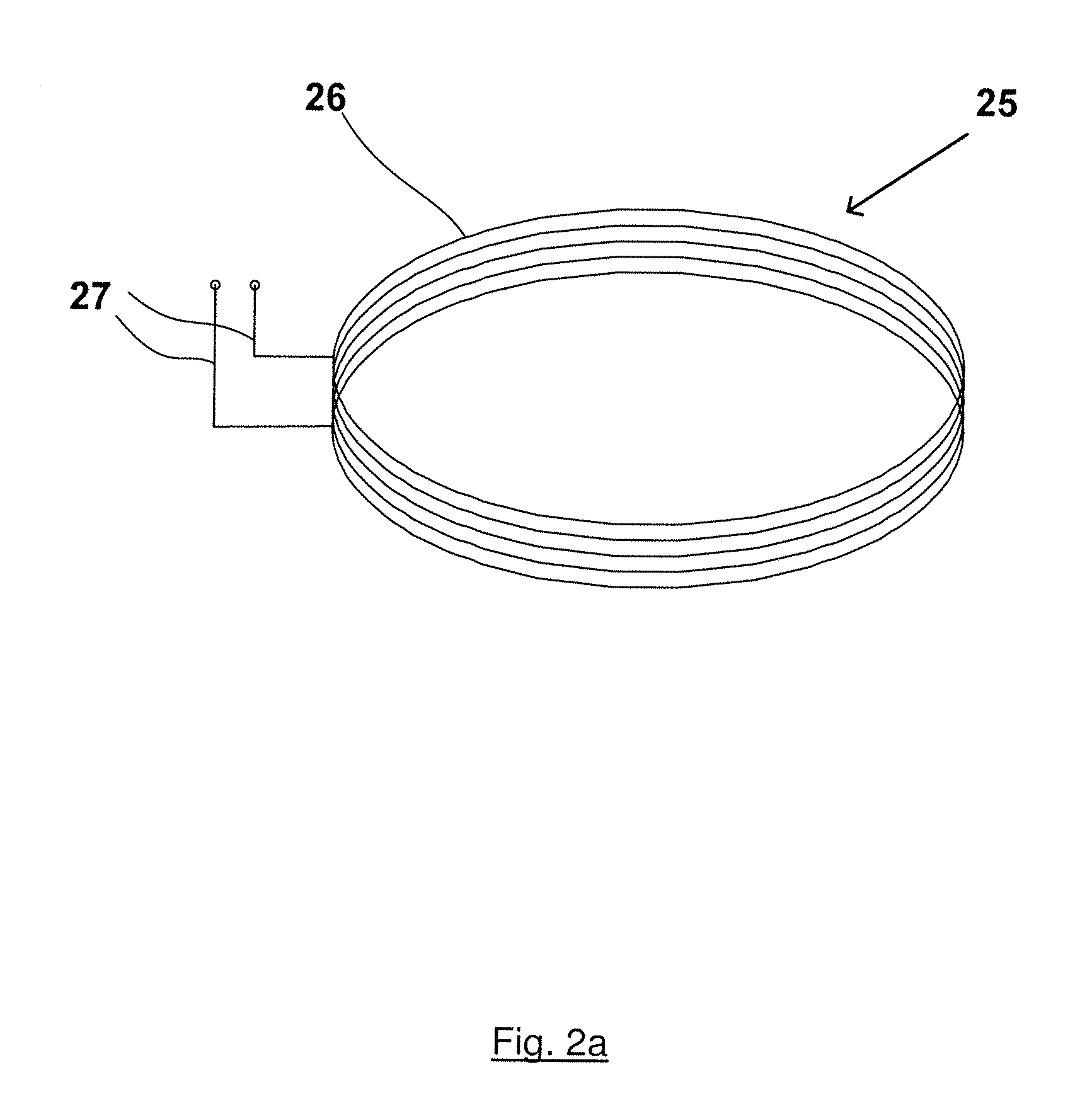
[0022]In further embodiments, a pair of closed loop antennas are provided, and are arranged so that both antennas lie substantially in co-axial alignment, i.e. so that each of the pair of closed loop antennas shares the same centre perpendicular axis but where there is an offset distance between the pair of antennas. The pair of closed loop antennas, thus arranged, defines a cylindrical volume which is sandwiched between each of the pair of closed loop antennas. In use, the antennas are connected in parallel so that electrical signals which are fed from the transmitter of the communications node are applied equally to both of the pair of closed loop antennas. The offset distance may be selected so that the pair of closed loop antennas forms a pair of Helmholtz coils. In this case, the variation of the magnetic field strength of magnetic signals inside the volume between the pair of antennas at a given moment in time is minimized.
[0023]A communications zone offering a reduced or minimized variation of the magnetic field strength of magnetic signals induced inside the communications zone has the advantage that complex power adjustment routines are not required to maintain connectivity over the full area or volume of the zone. In addition, a zone offering a reduced or minimized signal strength over its entire area or volume does not suffer from drop-out within areas of poor signal strength.

Problems solved by technology

It should be noted that underwater position determination by pre-programming of co-ordinates has a limited resolution, and position determination systems based on the use of homing devices also have several drawbacks.

Method used


Image

  • Underwater wireless communications hotspot
  • Underwater wireless communications hotspot
  • Underwater wireless communications hotspot

Examples


first embodiment

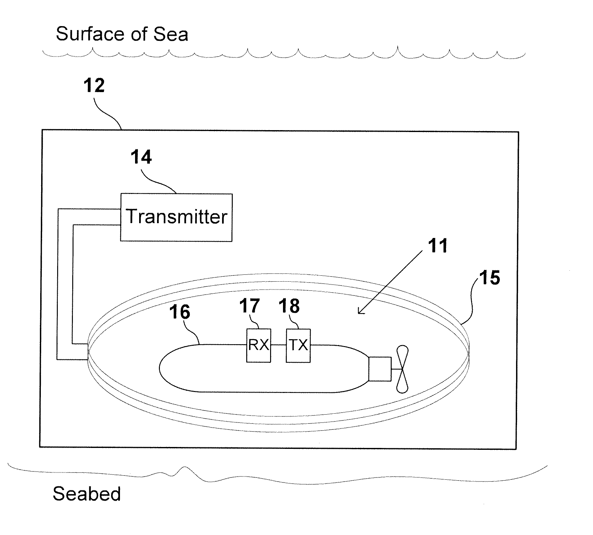
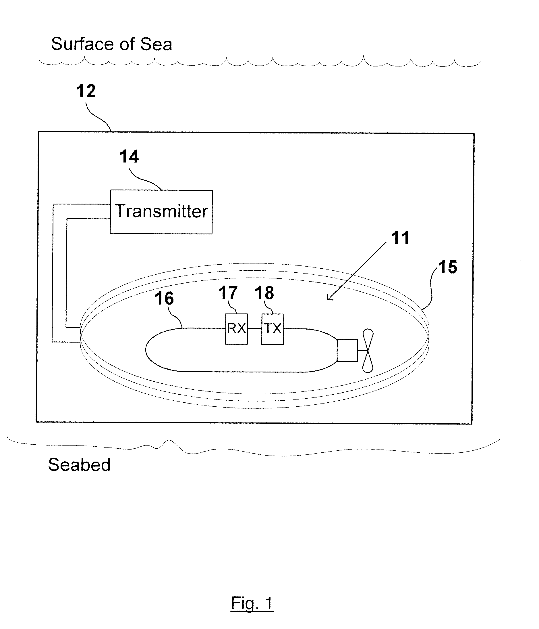
[0032]FIG. 1 shows a drawing of an underwater wireless communications hotspot according to the present invention. The underwater wireless communications hotspot of FIG. 1 comprises an active zone 11, a communications node 12 comprising a transmitter 14, connected to a closed loop antenna 15 which is wound from several turns of insulated electrically conducting wire. The active zone of the underwater wireless communications hotspot 11 of FIG. 1 is circumscribed by closed loop antenna 15. A mobile unit 16, comprising a built in receiver 17 is positioned within the active zone 11. Receiver 17, receives the magnetic signals transmitted inside loop antenna 15 of communications node 12 of FIG. 1. Mobile unit 16 further comprises a transmitter 18 which can transmit a handshaking signal to be received by communications node 12 so as to activate a process of data transfer between communications node 12 and mobile unit 16. Wire loop antenna 15 typically encloses a large area, in the order of ...

second embodiment

[0043]FIG. 7 shows a drawing of an underwater wireless communications hotspot according to the present invention. The underwater wireless communications hotspot of FIG. 7 comprises an active volume 71, a communications node 72 comprising a transmitter 74, connected to a pair of circular loop antennas 75a, 75b each of which is wound from several turns of insulated electrically conducting wire. The pair of circular loop antennas 75a, 75b have the same shape, and are positioned so there is an offset distance D between each loop and so that that the same centre perpendicular axes is common to each of the pair of circular loop antennas. The active volume of the underwater wireless communications hotspot 71 of FIG. 7 is defined by the cylindrical region between the pair of circular loop antennas 75a, 75b. A mobile unit 76, comprising a built in transceiver 77 is positioned within the active volume 71. Mobile unit 76 further comprises a transmitter 78 which can transmit a handshaking signa...


PUM


Abstract

The present invention provides an underwater wireless communications hotspot comprising an active zone which is circumscribed by a large closed loop antenna and within which wireless communication by means of electromagnetic signals can take place. The wireless communications hotspot of the present invention is suitable for data transfer between a communications node of the wireless hotspot and a receiver mounted on a mobile unit which is located inside the active zone of the hotspot. The wireless hotspot of the present invention provides a means for high bit rate data transfer from the communications node and the mobile unit, due to improved uniformity of coverage within the active zone of the hotspot and due to a reduction in the attenuation with distance compared to communications at positions outside the perimeter of a loop antenna.

Description

FIELD OF USE[0001]The present invention relates generally to the field of underwater wireless communications, and specifically to the provision of an underwater wireless hotspot or zone in which wireless communication by means of electromagnetic signaling can take place.BACKGROUND OF THE INVENTION[0002]Several improvements and technological advances have been made in the area of wireless telecommunications using electromagnetic signals over the last few decades. New products have been developed for commercial and industrial use exploiting various aspects of the electromagnetic spectrum to provide faster, more reliable communications at all levels. However, the recent technological advances apply almost exclusively to wireless communications in air. The field of underwater wireless communications has seen little development over the same timescale. Even today, the majority of underwater communications systems are still based on wired links.[0003]There are a limited range of wireless ...

Claims


Application Information

Patent Timeline
Patent Type & Authority Applications(United States)
IPC IPC(8): H04B13/02H04B5/00H01Q1/34
CPCH01Q1/04H04B13/02H01Q7/00H04B5/26H04B5/72H04B5/00
Inventor RHODES, MARKHYLAND, BRENDAN
Owner WIRELESS FIBER SYST
Learn More