Digital transmission system and digital transmission method

Active Publication Date: 2010-04-01
NIPPON TELEGRAPH & TELEPHONE CORP +1
View PDF9 Cites 36 Cited by
  • Summary
  • Abstract
  • Description
  • Claims
  • Application Information

AI Technical Summary

Benefits of technology

[0023]A third aspect of the invention provides a digital transmission system for transmitting a plurality of types of client signals having different bit rates by accommodating or multiplexing the signals in a digital frame, and outputting the client signals by separating accommodated or multiplexed signals from the received digital frame, the digital transmission system comprising: rate adjusting means for rate-adjusting the bit rate of the plurality of types of client signals to a bit rate range that can be accommodated in the digital frame transparently by inserting a dummy pattern, using a specific fixed frame, into the fixed frame for client signals other than the client signal having the highest bit rate among the plurality of types of client signals to increase the bit rate of the client signals.
[0024]A fourth aspect of the invention provides a digital transmission method for transmitting a plurality of types of client signals having

Problems solved by technology

However, these have problems such that both of them are predicated on a specific encoding method (8B/10B encoding) and that they are incapable of transparent transmission.
However, preparing transponders (optical transmission-reception modules or frame processing circuits) corresponding to the types of client signals leads to the problems of lack of flexibility in transponder arrangement and also high cost.
However, such methods in which the transparency is reduced have the problem that they cannot meet the recently increasing user's need for transparent transmission.
In addition, when multiplexing a client signal by a 40 Gbit/s OTN system, the difference in the bit rate cannot be permitted because a 10 Gbit/s signal is time-division mult

Method used


Image

  • Digital transmission system and digital transmission method
  • Digital transmission system and digital transmission method
  • Digital transmission system and digital transmission method

Examples


Example

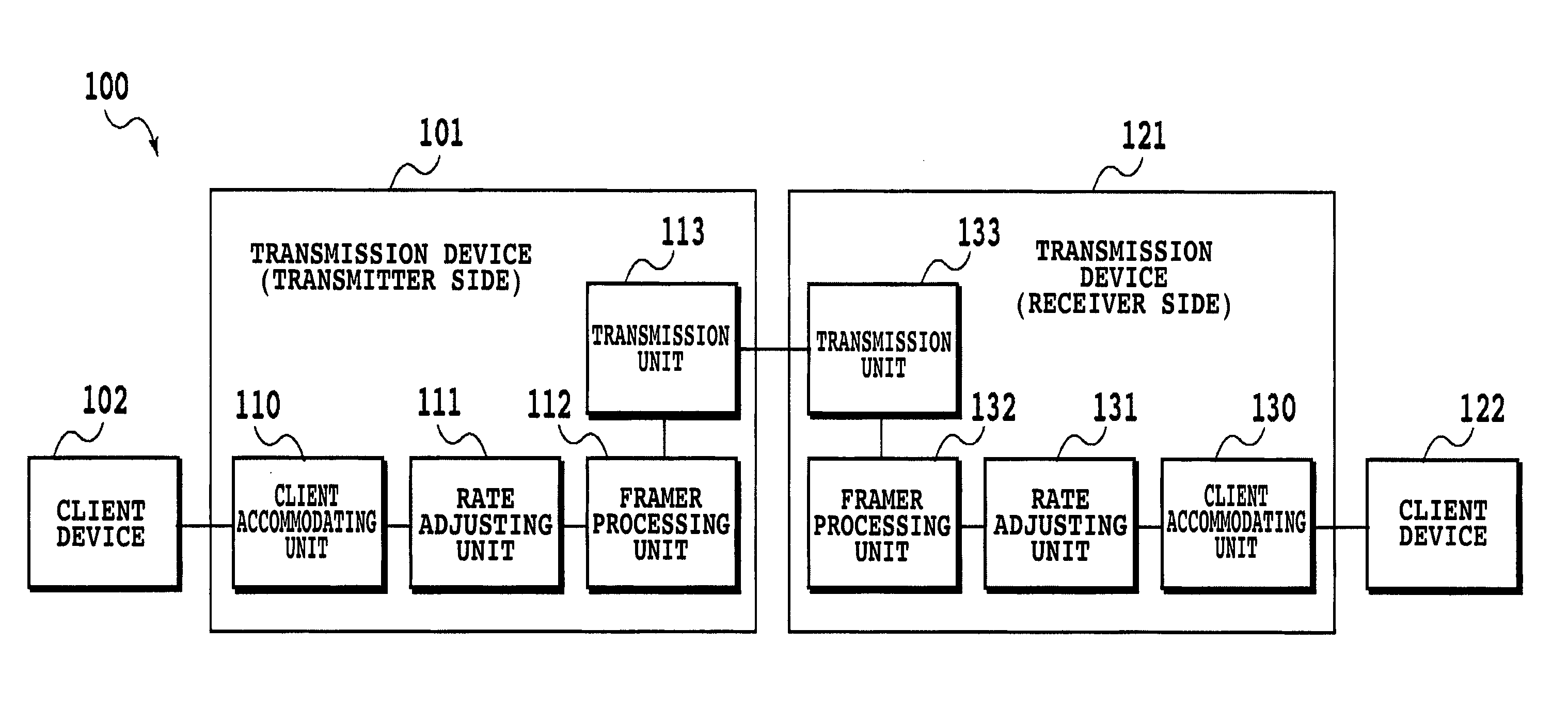
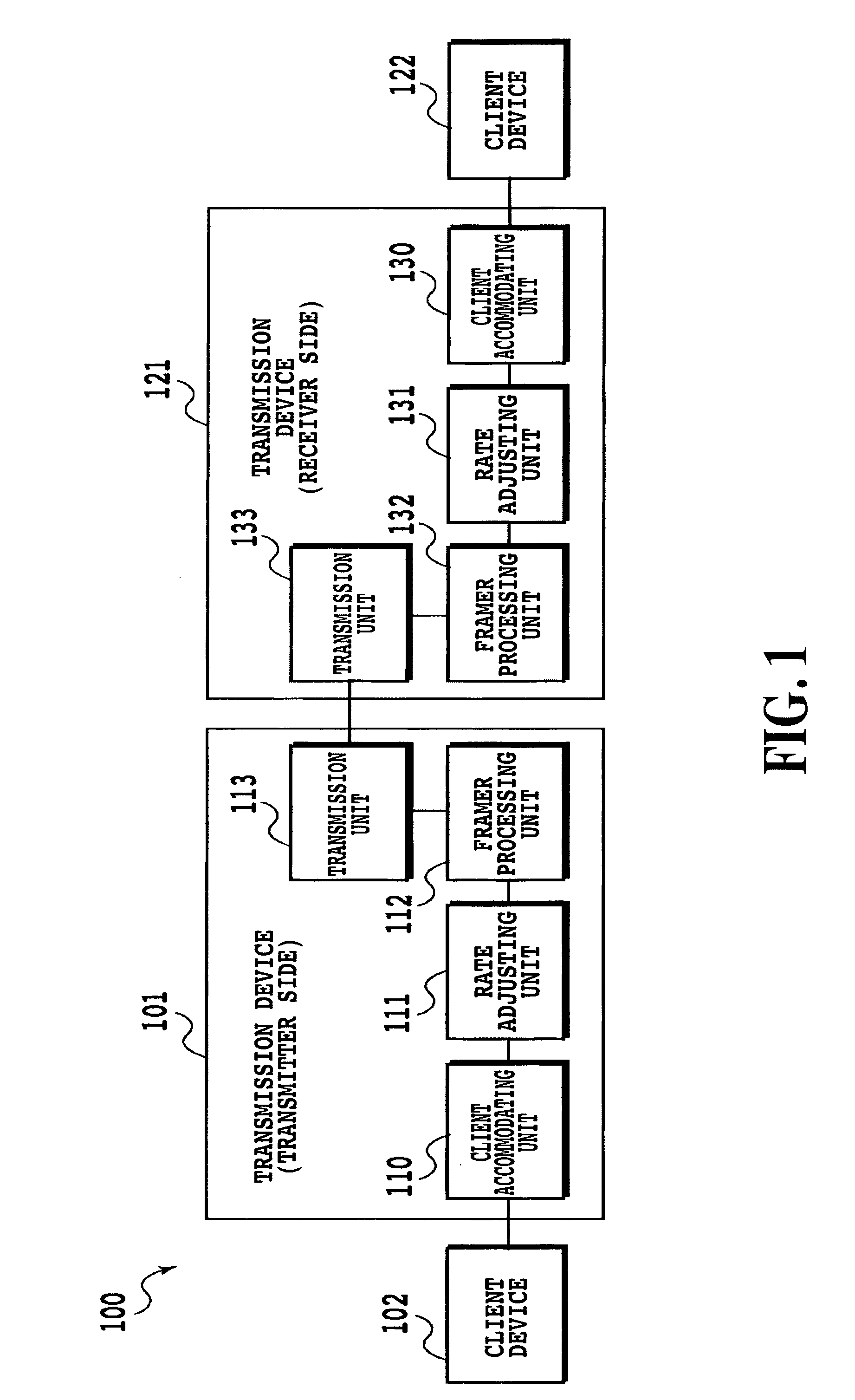
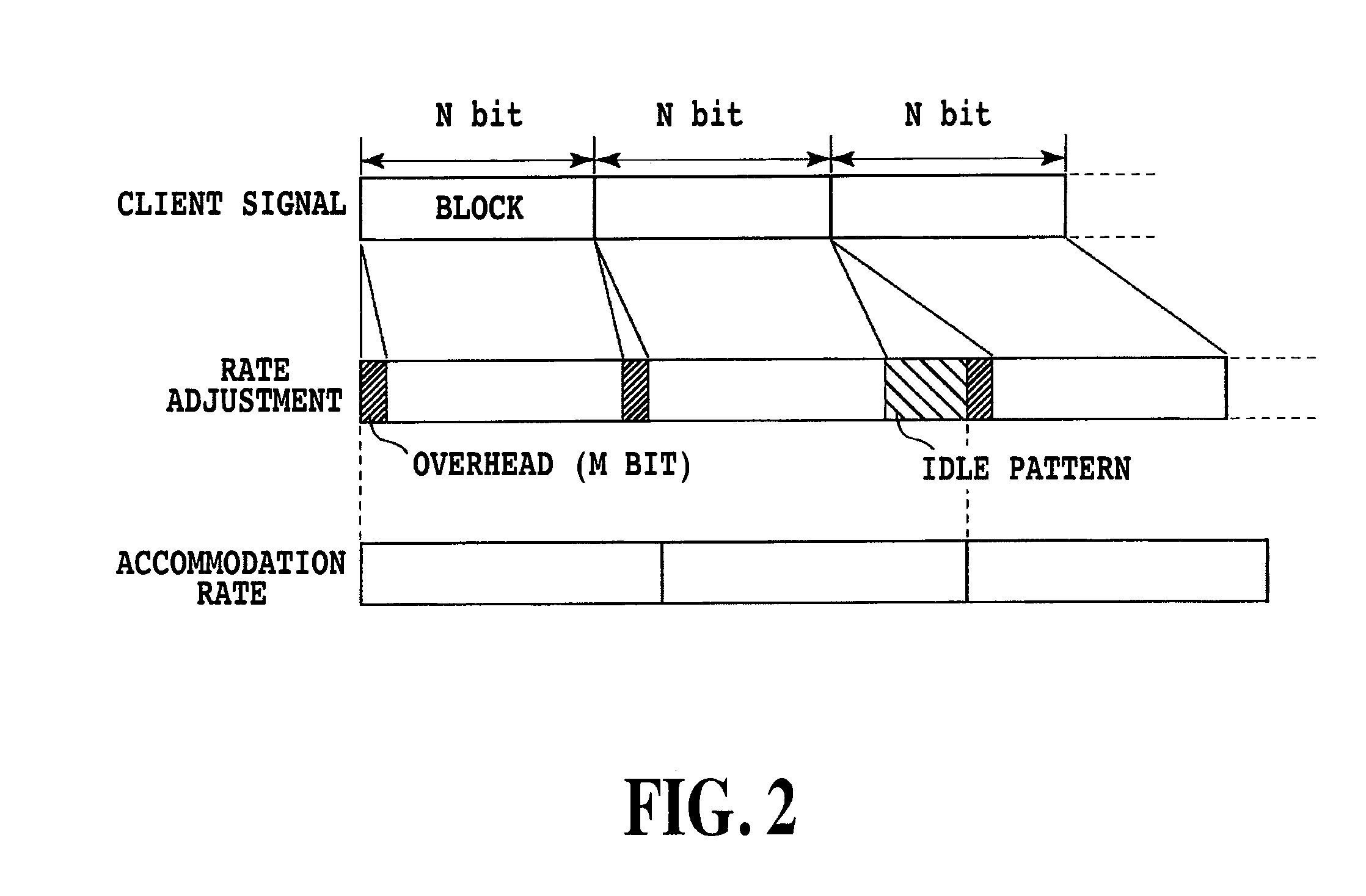
[0050]In the first and second aspects of the invention, when performing rate adjustment for a plurality of client signals as necessary, the bit rate of a client signal to be multiplexed is adjusted by inserting an idle pattern into the client signal, and thereafter, the signal is accommodated in a frame for transmission and multiplexed. More specifically, a plurality of client signals are encapsulated by using a frame structure for a specific rate adjustment, and also, an idle pattern is inserted into the client signal as necessary, to perform rate adjustment.

[0051]Moreover, in the first and second aspect of the invention, transparent transfer that is not predicated on a specific encoding method is achieved by accommodating, or accommodating and multiplexing, a bit string of a client signal directly in a payload portion, or by accommodating, or accommodating and multiplexing, the bit string in the payload portion after subjecting it to a reversible digital signal processing.

[0052]In...


PUM


Abstract

A digital transmission system includes at least a client device and a transmission device, and rate-adjusts the client signal transmitted from the client device to the transmission device before accommodating/multiplexing the signal in a frame. The transmission device includes a rate adjusting unit and a frame processing unit. The rate adjusting unit encapsulates the client signal by using a predetermined frame structure, inserts an idle pattern if necessary, and performs rate adjustment into the bit rate which can be contained in the frame. The frame processing unit accommodates/multiplexes the signal after the rate adjustment. The digital transmission system inserts a bit string of the client signal directly in a payload area of the digital frame, or accommodates and multiplexes it. Alternatively, a specific pattern is accommodated in the payload area, or accommodated and multiplexed after performing a reversible digital signal processing.

Description

TECHNICAL FIELD[0001]The present invention relates to a digital transmission system and a digital transmission method. More particularly, the invention relates to a digital transmission system and a digital transmission method in which a plurality of types of client signals are transmitted by accommodating or multiplexing the signals transparently.BACKGROUND ART[0002]Conventionally, digital transmission systems have been built to accommodate mainly telephone lines. SDH (Synchronous Digital Hierarchy), which is standardized by ITU-T, and SONET (Synchronous Optical Network), which is substantially the same standard as the SHD and is based on a U.S. ANSI standard, have been used as a digital hierarchy for transferring signals flowing through telephone lines efficiently, (cf. Non-patent Document 1).[0003]Currently, data traffic has being increasing because of the spread of the Internet and so forth, in addition to the conventional voice traffic, and the data traffic has come to account ...

Claims


Application Information

Patent Timeline
IPC IPC(8): H04J3/22
CPCH04J3/07H04J3/14H04J2203/0089H04J2203/0085H04J3/1664H04L1/24H04J2203/006H04L1/0061
Inventor KISAKA, YOSHIAKIOHARA, TAKUYAAISAWA, SHIGEKIMIYAMOTO, YUTAKATAKEI, KAZUHITOENDOH, YASUYUKIMIURA, YASUYUKINIKAIDO, TADANOBUTOMIZAWA, MASAHITO
Owner NIPPON TELEGRAPH & TELEPHONE CORP
Why Eureka
Try Eureka