A Realization Method of Ultrasonic Chirp Code Signal Based on Dynamic Pulse Width Modulation

A technology of pulse width modulation and implementation method, applied in the field of medical ultrasound coding, can solve the problems of increasing hardware circuit cost, inseparable from DAC converter, disadvantages, etc.

Active Publication Date: 2016-03-09
STATE GRID EAST INNER MONGOLIA ELECTRIC POWER CO LTD MAINTENANCE BRANCH +1
View PDF5 Cites 0 Cited by
  • Summary
  • Abstract
  • Description
  • Claims
  • Application Information

AI Technical Summary

Problems solved by technology

[0003] In recent years, due to the continuous development of encoding technology, various encoding methods have emerged. Due to the particularity of encoding signals, most of the hardware circuits for encoding signals are inseparable from DAC converters. Obviously, for a multi-channel For an ultrasound imaging system, each transmission channel needs to be equipped with a DAC converter, which will inevitably greatly increase the cost of the hardware circuit, and the hardware circuit is bulky, which is undoubtedly unfavorable for the realization of an efficient ultrasound imaging system

Method used


Image

  • A Realization Method of Ultrasonic Chirp Code Signal Based on Dynamic Pulse Width Modulation
  • A Realization Method of Ultrasonic Chirp Code Signal Based on Dynamic Pulse Width Modulation
  • A Realization Method of Ultrasonic Chirp Code Signal Based on Dynamic Pulse Width Modulation

Examples


Embodiment Construction

[0064] The preferred embodiments of the present invention will be described in detail below in conjunction with the accompanying drawings; it should be understood that the preferred embodiments are only for illustrating the present invention, rather than limiting the protection scope of the present invention.

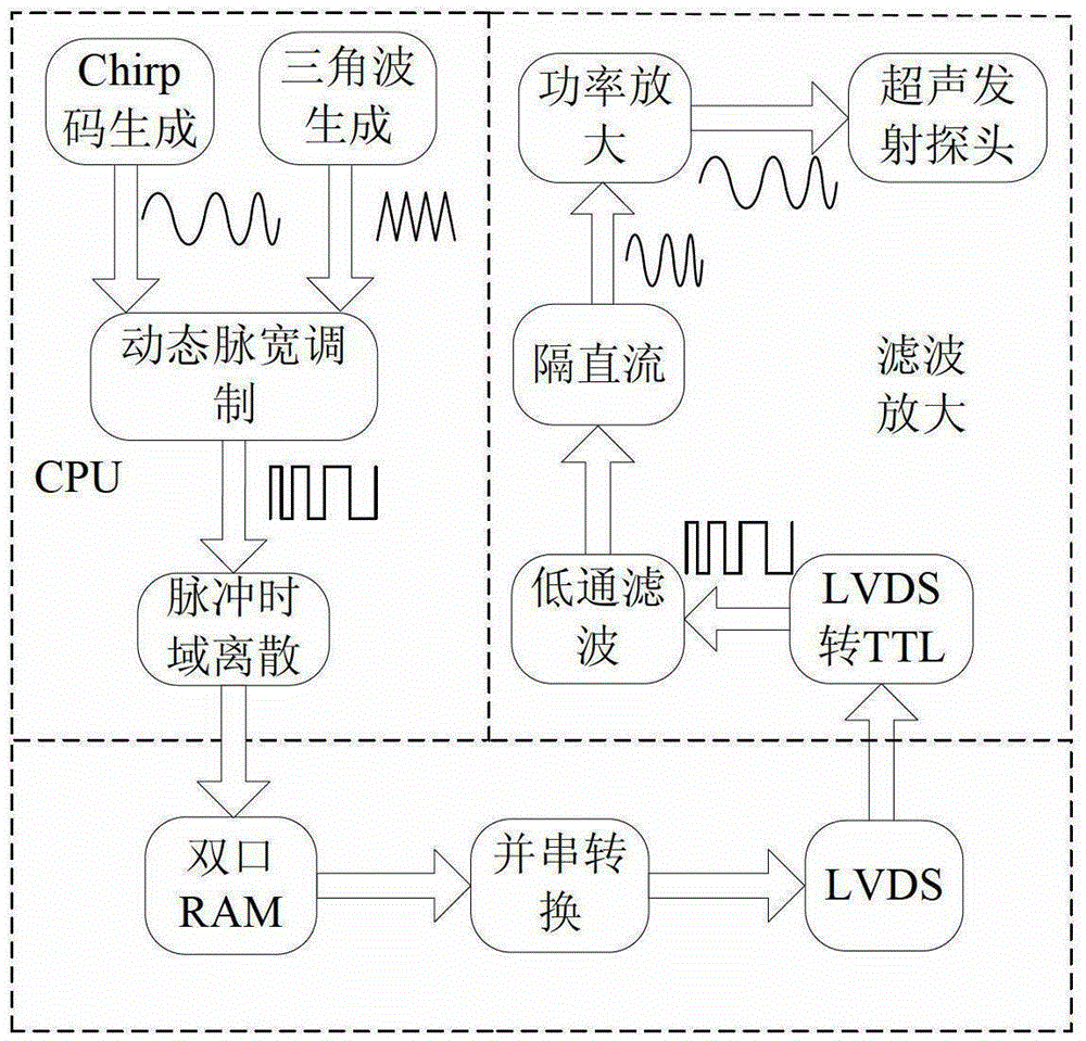
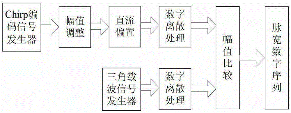
[0065] A method for realizing an ultrasonic Chirp code signal based on dynamic pulse width modulation comprises the following steps:

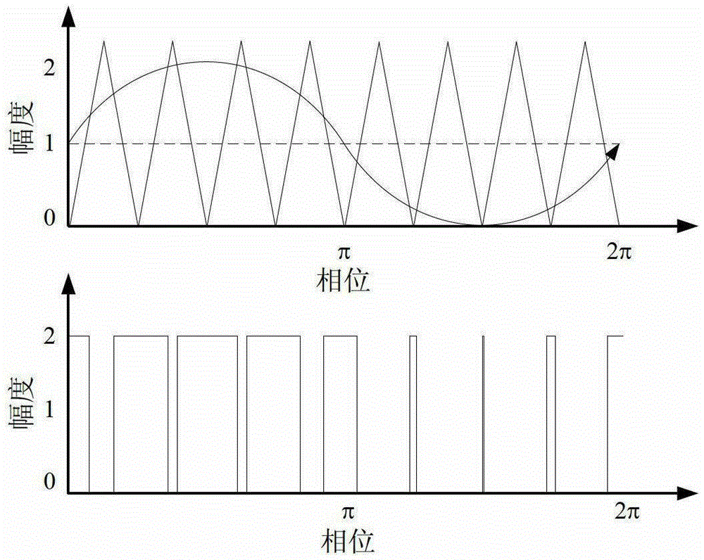
[0066] S1: Use the Chirp code to be transmitted to reduce the overall signal amplitude by A R times, and generate a unipolar Chirp code signal by shifting up by 1 unit; specifically include the following sub-steps;

[0067] S11: Set the time width of the chirp signal as T, the frequency width as B, and the central moment as t 0 , the center frequency is f 0 , the initial phase is φ S . According to the characteristics of the linear frequency modulation signal, the relationship between frequency and time can be written as

[0068] ...


PUM


Abstract

The invention discloses an ultrasound Chirp code signal implementation method based on dynamic pulse width modulation. The ultrasound Chirp code signal implementation method based on the dynamic pulse width modulation comprises S1, generating an unipolar coded signal according to a Chirp code to be transmitted; S2, utilizing a dynamic pulse width modulation technology to modulate the unipolar coded signal and obtaining a high frequency digital pulse sequence through pulse time domain discretization; S3, storing the high frequency digital pulse sequence into a dual-port RAM (random-access memory) of an FPGA (Field Programmable Gate Array) chip; S4, generating read control through an FPGA, sequentially calling out storage values of the high frequency digital pulse sequence in the dual-port RAM, subjecting the storage values to parallel-serial conversion, and outputting a serial high frequency digital pulse sequence through an LVDS (Low-Voltage Differential Signaling) inside the FPGA; and S5, utilizing an LVDS to TTL (Transistor-Transistor Logic) module to subject the serial high frequency digital pulse sequence to level conversion and obtaining an ultrasound-transmitted Chirp mode signal after low-pass filtering, DC (direct current) blocking processing and power amplification. The ultrasound Chirp code signal implementation method based on the dynamic pulse width modulation can generate the Chirp signal, also has general applicability to the generation of other coded signals in an ultrasound imaging field, and compared with a traditional coding excitation circuit, can reduce the complexity of an ultrasound coded signal generation circuit.

Description

technical field [0001] The invention relates to the field of medical ultrasonic coding, in particular to a method for realizing an ultrasonic Chirp code signal based on dynamic pulse width modulation. Background technique [0002] In medical ultrasound imaging, echo signals in non-source directions introduce a lot of noise and clutter, resulting in image quality degradation. At present, encoding technology is generally used to increase the transmission power and perform pulse compression on the received echo signal to reduce the interference of clutter power such as noise and improve the signal-to-noise ratio (SNR) in the direction of the source. Compared with the traditional short pulse as the excitation signal, the encoding technology has a good processing effect on the ultrasonic echo signal. After the transmitted signal is encoded and excited, the transmitted power can be increased without increasing the signal amplitude, which greatly improves the detection depth and r...

Claims


Application Information

Patent Timeline
Patent Type & Authority Patents(China)
IPC IPC(8): H04N19/42A61B8/00
Inventor 王平邹强鑫王林泓王思奇
Owner STATE GRID EAST INNER MONGOLIA ELECTRIC POWER CO LTD MAINTENANCE BRANCH
Why Eureka
Try Eureka