Tooth brace visual indicia

a technology of visual indicia and tooth brace, which is applied in the field of tooth brace systems, can solve the problems of many patients, especially children, who dislike the appearance of the brace when applied, and achieve the effect of improving aesthetic quality and overcoming drawbacks and deficiencies

Inactive Publication Date: 2006-12-28
INGENIOUS CONCEPTS
View PDF9 Cites 34 Cited by
  • Summary
  • Abstract
  • Description
  • Claims
  • Application Information

AI Technical Summary

Benefits of technology

[0007] It is, therefore, one object of the present invention to provide tooth brace visual indicia that overcomes the drawbacks and deficiencies of the prior art. It is another object of the present invention to provide tooth brace visual indicia that result in an improved aesthetic quality to a human brace. It is a still further object of the present invention to provide tooth brace visual indicia that may be removably attachable to at least one component of a brace system.

Problems solved by technology

While the patient certainly desires and enjoys the results of utilizing braces, many patients, particularly children, dislike the appearance of the brace when applied.

Method used


Image

  • Tooth brace visual indicia
  • Tooth brace visual indicia
  • Tooth brace visual indicia

Examples


first embodiment

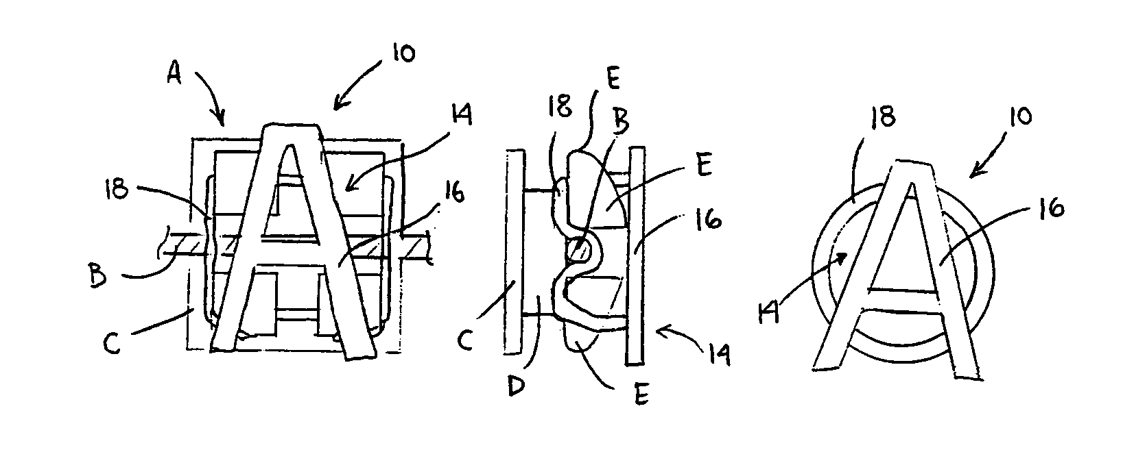
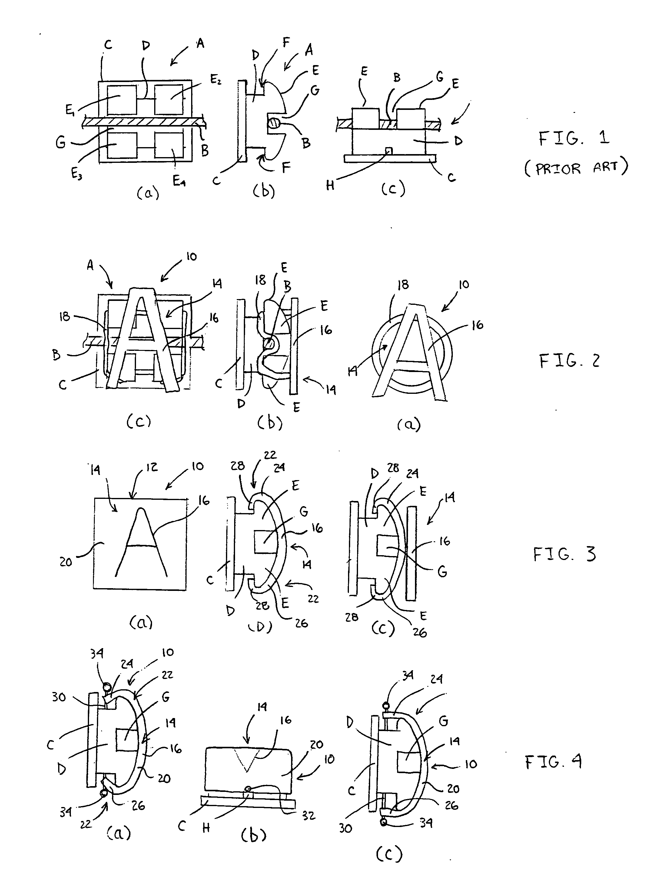
[0049] As seen in a first embodiment in FIGS. 2a-2c, the attaching carrier includes visual indicia 14 in the form of a symbol 16, which is attached to or integrally formed with an elastic ring 18. The symbol 16 may be either rigid or elastic, depending upon the application and the amount of stretching involved. The elastic ring 18 is similar in size and shape to an A-lastic, which is the elastic band or ligature and typically used to secure the brace wire B to the brace bracket A. In use, the attaching carrier 12 is positioned centrally on the face of the brace bracket A, and the elastic ring 18 is stretched over one or more of the wing elements E and allowed to contract or retract into one or more of the respective ring element grooves F. Accordingly, the attaching carrier 12 is secured to the brace bracket A and oriented such that the symbol 16 is visible to an observer when the user opens his or her mouth.

[0050] When attached, the elastic ring 18 of the attaching carrier 12 serve...

third embodiment

[0056] As discussed above in connection with the previous embodiment, the engagement member 22 of this third embodiment can be used to secure the brace wire B in the brace bracket groove G, obviating the need for an A-lastic. In another arrangement, and as illustrated in FIG. 4c, the first engagement member 24 and second engagement member 26 are not sloped to mate directly over the wing elements E. Such contouring or sloping would not be required since the pin 30 serves to secure the attaching carrier 12 to the brace bracket A.

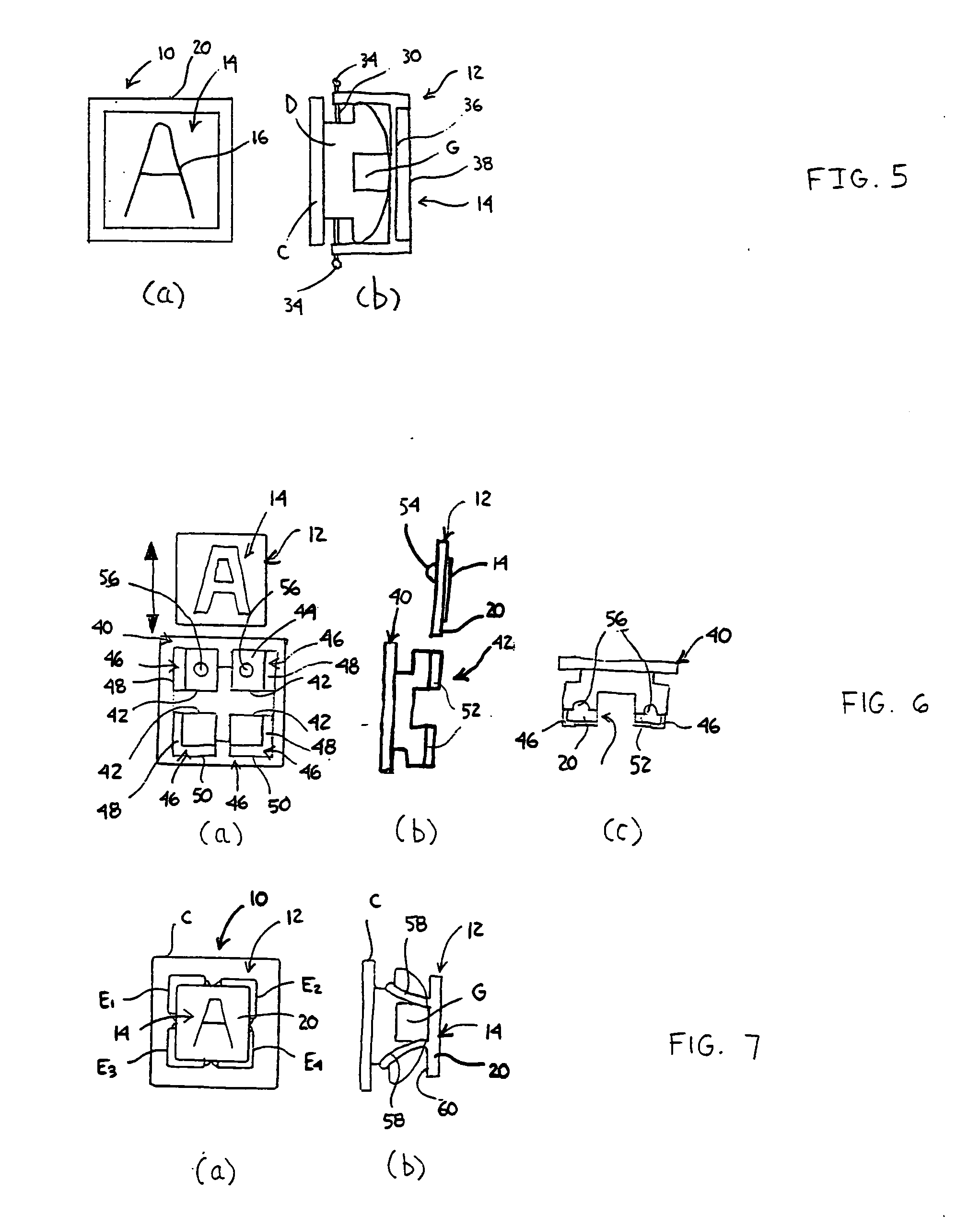
[0057] A fourth embodiment of the indicia apparatus 10 of the present invention is shown in FIGS. 5a-5b. The fourth embodiment is similar to the third embodiment discussed above, in that an attaching carrier substrate 20 and pin 30 arrangement secures the attaching carrier 12 to the brace bracket A. However, in the present embodiment, the attaching carrier substrate 20 is magnetized. Further, the attaching carrier substrate 20 has a visual indicia slot 36 loca...

fourth embodiment

[0058] As discussed above, and in this embodiment, the attaching carrier substrate 20 may also serve to secure the brace wire B in the brace bracket groove G. However, in this embodiment, the user may remove the visual indicia substrate 30 (or visual indicia 14) from the visual indicia slot 36 and magnetically place other visual indicia substrates 38 in the visual indicia slot 36. One benefit of this fourth embodiment is that the entire attaching carrier substrate 20 and pin 30 structure need not be removed from the brace bracket A in order to change the visual indicia 14 visible on the brace bracket A.

[0059] It is envisioned that the attaching carrier 12 can be uniformly or diversely colored. For example, in the first embodiment discussed above, it would be preferable that the elastic ring 18 be clear, while the symbol 16 be a highly visible color, such as a blaze orange. This would increase the visibility and effect of the present invention. Similarly, in any of the embodiments di...


PUM


Abstract

Tooth brace visual indicia for a brace system for human teeth, including an indicia apparatus for engagement with at least one component of a brace system for human teeth. The indicia apparatus includes an attaching carrier removably attachable to the at least one component of the brace system, and the attaching carrier is in operational engagement with or integrally formed with visual indicia. A visual indicia system and a method of providing visual indicia are also disclosed.

Description

CROSS REFERENCE TO RELATED APPLICATIONS [0001] This application claims priority under 35 U.S.C. § 119(e) from provisional U.S. Patent Application No. 60 / 690,744, filed Jun. 15, 2005, the contents of which are incorporated herein by reference.BACKGROUND OF THE INVENTION [0002] 1. Field of Invention [0003] The present invention relates generally to brace systems for adjusting human teeth and, in particular, to tooth brace visual indicia, an indicia apparatus and a method of providing visual indicia for a brace system. [0004] 2. Description of the Prior Art [0005] In the field of dentistry and orthodontics, braces are used to assist in adjusting the angle and displacement of human teeth. As the technology of manufacturing and applying braces to human teeth develops, the market and class of target patients increase accordingly. Both children and adults utilize braces to straighten their teeth for aesthetic reasons. Further, braces are also used to correct and / or prevent medical mishaps ...

Claims


Application Information

Patent Timeline
Patent Type & Authority Applications(United States)
IPC IPC(8): A61C3/00
CPCA61C7/00A61C13/082A61C7/12
Inventor SMITH, FRED
Owner INGENIOUS CONCEPTS
Why Eureka
Try Eureka