Board, connector, connector detaching device and method of detaching connector

a technology of detachable connectors and connectors, which is applied in the direction of line/current collector details, printed circuits, electrical apparatuses, etc., can solve the problems of terminals being broken and remaining on the board, affecting the service life of the board, and requiring a lot of time and troubl

Inactive Publication Date: 2006-12-28
FUJITSU LTD
View PDF9 Cites 4 Cited by
  • Summary
  • Abstract
  • Description
  • Claims
  • Application Information

AI Technical Summary

Benefits of technology

[0040] According to the present invention, the connector is detached from the board by a simple mechanism without the breakage of the board and the connector.

Problems solved by technology

However, when failures occur in part of the inner components of a server, a communication device, etc. and inspection, replacement and the like of the components are performed, it becomes necessary to extract the connector from the printed circuit board.
Because as described above, a connector provided with many terminals is firmly fixed to a thin printed circuit board, there is a possibility that when the connector is to be taken out with hand, the through holes might be forced open, resulting in the breakage of the board, and that the terminals might be broken and remain within the board.
Although it is conceivable to disassemble a connector and to take out the terminals one by one in order to avoid the breakage of a board, this takes much trouble and time.
Such difficulty in detaching a connector prevents the reuse of printed circuit boards and connectors.
However, in the method shown in part (A) of FIG. 1, it is necessary that the housing 21 of the connector 20 have the gripping area 21a having a width and strength large enough for catching the jig 30 above the portion from which the terminals 22 project, thereby posing the problem that the thickness and width of the connector 20 increase considerably.
However, in the method shown in the Japanese Patent Laid-Open No. 9-199821, the terminals of a connector are fabricated from an expensive shapememory alloy, thereby posing the problem that the cost of the whole device rises.
In the method shown in the Japanese Patent Laid-Open No. 8-88038, it is necessary that the minute portion where the connector and the board are in contact with each other be subjected to special working, thereby posing the problem that the manufacturing of the connector and the board becomes complicated.

Method used


Image

  • Board, connector, connector detaching device and method of detaching connector
  • Board, connector, connector detaching device and method of detaching connector
  • Board, connector, connector detaching device and method of detaching connector

Examples


first embodiment

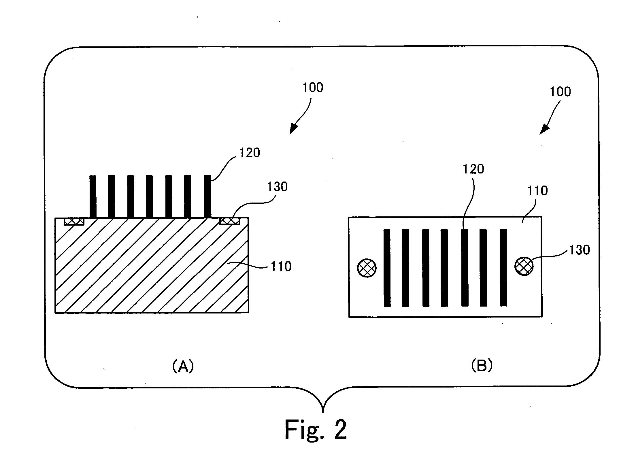
[0049]FIG. 2 is a diagram to show a connector in the present invention.

[0050] Part (A) of FIG. 2 shows a side view of a connector 100, and part (B) of FIG. 2 shows a view of the connector 100 shown in part (A) of FIG. 2 as viewed from above.

[0051] As shown in part (A) of FIG. 2, the connector 100 is constituted by a housing 110 and multiple terminals 120 held by the housing 110, and these multiple terminals 120 project from one surface of the housing 110. As shown in part (B) of FIG. 2, a reinforcing portion 130 having high strength is provided within the surface of the housing 110 from which the terminals 120 project. The housing 110 corresponds to an example of the “frame” in the connector of the present invention, the terminals 120 correspond to an example of the “terminal” in the connector of the present invention, and the reinforcing portion 130 corresponds to an example of the “high-strength section” in the connector of the present invention.

[0052]FIG. 3 is a view of a board...

second embodiment

[0067]FIG. 6 is a diagram to show a connector in the present invention.

[0068] As shown in part (A) of FIG. 6, in a connector 500 of this second embodiment, the number of terminals 120 is larger than in the connector 100 of the first embodiment shown in FIG. 2, and the transverse length in which the terminals 120 are arrayed increases accordingly. Also, as shown in part (B) of FIG. 6, in the connector 500 in a position inward from the position where a reinforcing portion 130 is provided, there is made a through hole 540a which pierces through a housing 510. When the connector 500 is attached to a board 200, a through hole 540a is filled by the board 200. The portion 540 where this through hole 540a is made corresponds to an example of the “through section” in a connector of the present invention.

[0069]FIG. 7 is a diagram to show a connector detaching device in the second embodiment of the present invention.

[0070] Although the connector detaching device of this embodiment has almost...


PUM


Abstract

A connector detaching device detaches a connector that has a terminal projecting from a frame thereof and is attached to a board by insertion of the terminal into the board. The connector is attached to the board having a through hole filled by the frame of the connector attached to the board. The device includes: a board supporting jig that has a base and plural supporting arms extending from the base in an arrayed manner and supports the board with the plural supporting arms from a surface of the board to which the connector is attached by straddling the connector; and a push-out jig that has an insertion rod having a diameter smaller than the through hole and pushes the frame of the connector by the insertion rod through the through hole from a side reverse to the side of the surface to which the connector is attached.

Description

BACKGROUND OF THE INVENTION [0001] 1. Field of the Invention [0002] The present invention relates to a board to which a connector is attached, a connector which is attached to a board, and a connector detaching device which detaches a connector attached to a board, and a method of detaching a connector. [0003] 2. Description of the Related Art [0004] A connector which is attached to a printed circuit board which is built in a server, a communication device, etc. and connects the printed circuit board and an electric circuit together, has hitherto been widely used. Usually, a connector is provided with multiple terminals which are connected to each of the multiple electric lines extending from an electric circuit, these multiple terminals are each inserted into multiple through holes provided in a printed circuit board, the terminals are further fixed, by soldering, for example, whereby the printed circuit board and the electric circuit are electrically connected together via the con...

Claims


Application Information

Patent Timeline
Patent Type & Authority Applications(United States)
IPC IPC(8): H01R12/00
CPCH01R43/205H05K3/306H05K2203/176H05K2203/0195H05K2201/09063
Inventor MURATA, YOKOKOJIMA, SETUO
Owner FUJITSU LTD
Why Eureka
Try Eureka