Wireless transmission apparatus, polar modulation transmission apparatus, and wireless communication apparatus

a transmission apparatus and polar modulation technology, applied in the direction of climate sustainability, electrically long antennas, antennas, etc., can solve the problems of low power efficiency, power consumption of bias current, and the problem of describing below

Inactive Publication Date: 2006-12-28
PANASONIC CORP
View PDF16 Cites 72 Cited by
  • Summary
  • Abstract
  • Description
  • Claims
  • Application Information

AI Technical Summary

Benefits of technology

[0021] It is therefore an object of the present invention to improve power efficiency at the time of transmission of EDGE modulation scheme signals in multi-mode compatible wireless transmission ...

Problems solved by technology

However, with the wireless transmission apparatus of the related art described above, the problems described below are encountered from the viewpoint of power efficiency of th...

Method used


Image

  • Wireless transmission apparatus, polar modulation transmission apparatus, and wireless communication apparatus
  • Wireless transmission apparatus, polar modulation transmission apparatus, and wireless communication apparatus
  • Wireless transmission apparatus, polar modulation transmission apparatus, and wireless communication apparatus

Examples


embodiment 1

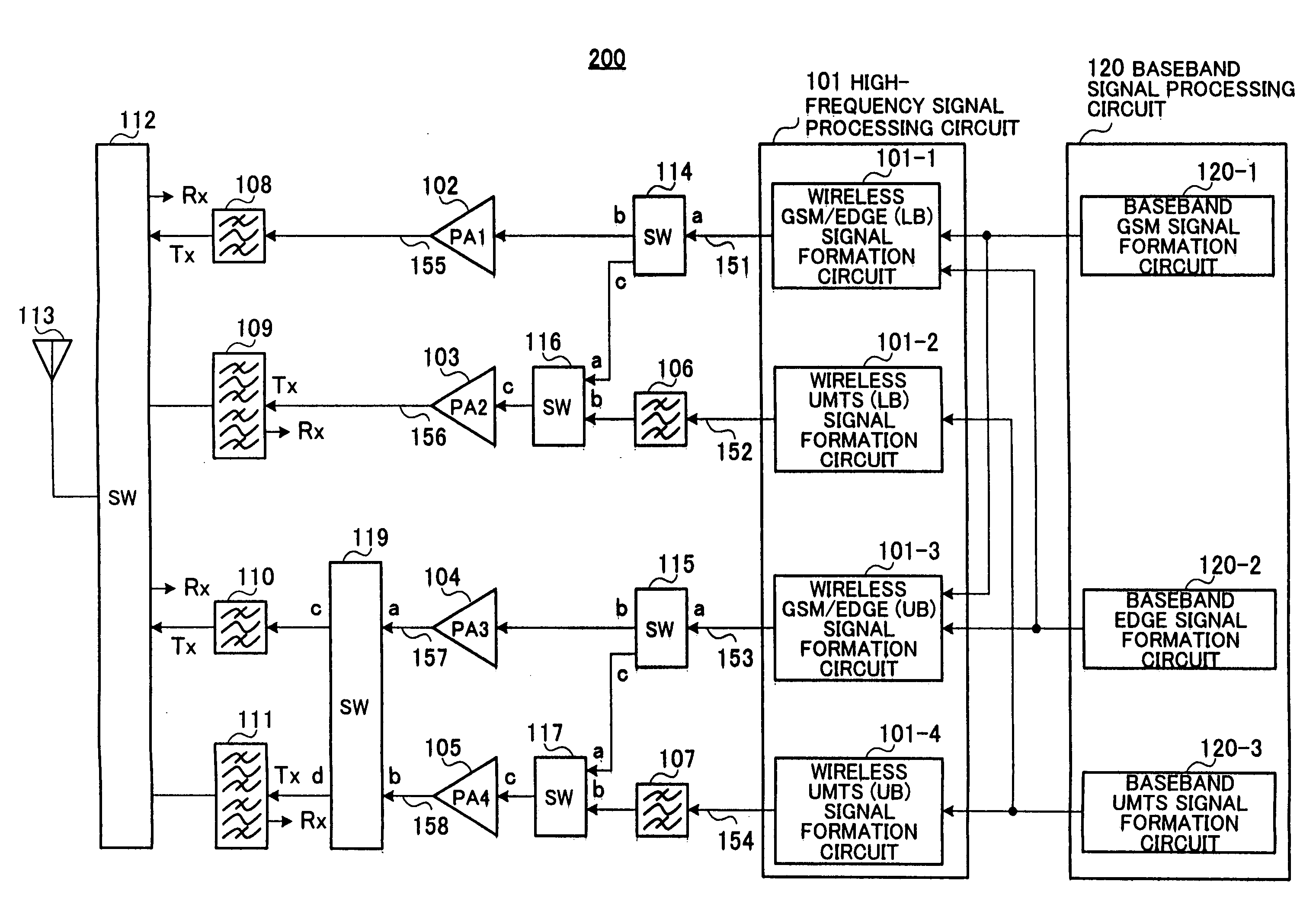
[0033] A configuration for a wireless transmission apparatus according to Embodiment 1 of the present invention is shown in FIG. 3. In FIG. 3, blocks having the same functions as in FIG. 1 are given the same reference numerals and description thereof is omitted.

[0034] Wireless transmission apparatus 200 is a so-called multi-mode compatible wireless transmission apparatus for wirelessly transmitting GSM modulation scheme, EDGE modulation scheme and UMTS modulation scheme signals.

[0035] The transmission frequency range of wireless transmission apparatus 200 of this embodiment is 824 to 849 MHz at low-frequency bands (LB) for either of the GSM / EDGE and UMTS modulation schemes but at high-frequency bands (UB) the transmission frequency range is 1710 to 1785 for GSM / EDGE modulation schemes and 1850 to 1910 MHz (refer to 3GPP standard) for UMTS modulation schemes.

[0036] Wireless transmission apparatus 200 has a one input / two outputs switching switch 114 for sorting, of wireless GSM / EDG...

embodiment 2

[0057] A configuration for a polar modulation transmission apparatus according to Embodiment 2 is shown in FIG. 6, with portions corresponding to FIG. 3 being given the same reference numerals.

[0058] Polar modulation transmission apparatus 300 of this embodiment differs from wireless transmission apparatus 200 of Embodiment 1 with regards to the following two points.

[0059] The first point is that, whereas orthogonal modulation was carried out at high-frequency signal processing circuit 101 in Embodiment 1, in this embodiment, signal processing is carried out by high-frequency signal processing circuit 310 based on a polar modulation scheme.

[0060] The second point is that the transmission frequency range in this embodiment is such that the low-frequency band (LB) is 824 to 849 MHz, and the high-frequency band (UB) is 1850 to 1910 MHz (refer to 3GPP standard) for both GSM / EDGE and UMTS modulation schemes.

[0061] Polar modulation is a scheme of adding amplitude modulation by multipl...


PUM


Abstract

A wireless transmission apparatus of multi-mode operation with superior power efficiency is provided. Switches (115 and 117) are switched over in such a manner that a modulation signal outputted from a wireless GSM/EDGE (UB) signal formation circuit (101-3) of a high-frequency signal processing circuit (101) is outputted to a high-frequency power amplifier (104) at the time of output of a GSM modulation signal, and is outputted to a high-frequency amplifier (105) at the time of output of an EDGE modulation signal. As a result, the EDGE modulation signal is power amplified using a high-frequency power amplifier (105) for an UMTS modulation signal use that is compatible with regards to the EDGE modulation signal and the maximum output power and presence or absence of envelope fluctuation. It is therefore possible to amplify the EDGE modulation scheme wireless signal with high efficiency.

Description

BACKGROUND OF THE INVENTION [0001] 1. Field of the Invention [0002] The present invention relates to wireless transmission apparatus, polar modulation transmission apparatus, and wireless communication apparatus capable of transmitting wireless signals of a plurality of schemes such as a GSM modulation scheme, EDGE modulation scheme and UMTS modulation scheme. [0003] 2. Description of the Related Art [0004] Conventionally, in recent years, several different communication schemes have existed in the world as communication schemes for mobile telephones. However, against the backdrop of a dramatic worldwide growth in mobile telephones in recent years, demand for so-called multi-mode terminals compatible with a number of communication schemes rather than a single communication scheme has dramatically increased. [0005] A multi-mode communication scheme enabling both a UMTS modulation scheme and GSM-EDGE modulation scheme may be given as an example of a multi-mode communication scheme. Th...

Claims


Application Information

Patent Timeline
IPC IPC(8): H04B1/04H04B1/02
CPCH04B1/0483Y02B60/50H04B1/406
Inventor HARA, YOSHIHIROMORIMOTO, SHIGERUMATSUURA, TORUADACHI, HISASHIISHIDA, KAORU
Owner PANASONIC CORP
Why Eureka
Try Eureka