Wireless communication apparatus and phase-variation correction method

a communication apparatus and phase-variation correction technology, applied in electrical apparatus, radio transmission, substation equipment, etc., can solve the problems of limiting the number of channels that can communicate simultaneously, limiting the capacity of channels, and estimation cannot be accurately performed, so as to improve the accuracy of phase-variation estimation, improve reception accuracy, and improve the effect of reception accuracy

Inactive Publication Date: 2006-12-28
FUJITSU LTD
View PDF10 Cites 20 Cited by
  • Summary
  • Abstract
  • Description
  • Claims
  • Application Information

AI Technical Summary

Benefits of technology

[0011] Another object of the present invention is to correct phase variation in each radio receiving circuit based upon an estimated phase variation and improve reception accuracy by carrying out beam forming oriented in the direction of signal arrival.
[0012] A further object of the present invention is to implement correction of variation and estimation of arrival direction through a simple arrangement in multicarrier modulation schemes (inclusive of OFDM) viewed as promising in future wireless communications.
[0023] In accordance with the present invention, narrow-band signals are extracted from baseband signals antenna by antenna, the phase variation of each radio receiving circuit is estimated using the narrow-band signals of each antenna, and phase is corrected for so as to invert the phase of the phase variation, thereby correcting for phase variation in each radio receiving circuit. As a result, it is unnecessary to add on special circuits for estimating phase variation, as is required in the prior art, and therefore phase variation in each radio receiving circuit can be estimated and corrected for through a simple arrangement.
[0024] Further, in accordance with the present invention, direction of signal arrival is estimated using narrow-band signals of at least two antennas, receive beam-forming processing is applied to each phase-variation-corrected signal based upon the direction of signal arrival, and receive data is demodulated from each receive signal that has undergone beam-forming processing. This makes it possible to improve reception accuracy.
[0025] Further, the present invention is such that each carrier signal of a multicarrier or each subcarrier signal of OFDM is used as the narrow-band signal of each antenna if the system is a multicarrier communication system. If the system is a wide-band single-carrier system, a narrow-band signal that has been extracted using a filter can be used. As a result, regardless of whether the system is for multicarrier communication or wide-band single-carrier transmission, phase variation of each radio receiving circuit and direction of signal arrival can be estimated and reception accuracy can be improved by correcting for variation and executing beam-forming processing.
[0026] Further, in accordance with the present invention, the accuracy of phase-variation estimation can be improved as well as the accuracy of reception by (1) using narrow-band signals of two carriers of maximum frequency spacing as the narrow-band signals of each of the antennas, or (2) obtaining phase variations with regard to a plurality of sets of carriers, weighting the phase variation of each set based upon the reception signal levels of the carriers, and adopting a weighted mean value as true phase variation, or (3) obtaining phase variations with regard to a plurality of sets of carriers, weighting the phase variation of each set based upon frequency spacing of the carriers, and concluding that the weighted mean value is the true phase variation.

Problems solved by technology

However, signals from other communicating channels interfere and, as a result, there is a limit on the number of channels that can communicate simultaneously, i.e., there is a limit on channel capacity.
Even if the beam-arrival direction (the direction of the mobile station) is estimated using these signals imparted with different amplitude and phase characteristics, estimation cannot be performed accurately.
These items of hardware complicate the system and are not necessarily the best in terms of cost.

Method used


Image

  • Wireless communication apparatus and phase-variation correction method
  • Wireless communication apparatus and phase-variation correction method
  • Wireless communication apparatus and phase-variation correction method

Examples


first embodiment

[0054] (B) First Embodiment

[0055]FIG. 5 is a diagram illustrating the structure of a radio receiving apparatus according to a first embodiment of the present invention. Components identical with those of FIGS. 1 and 4 are designated by like reference characters.

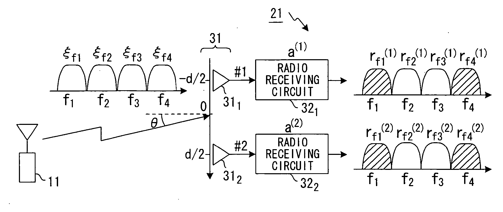
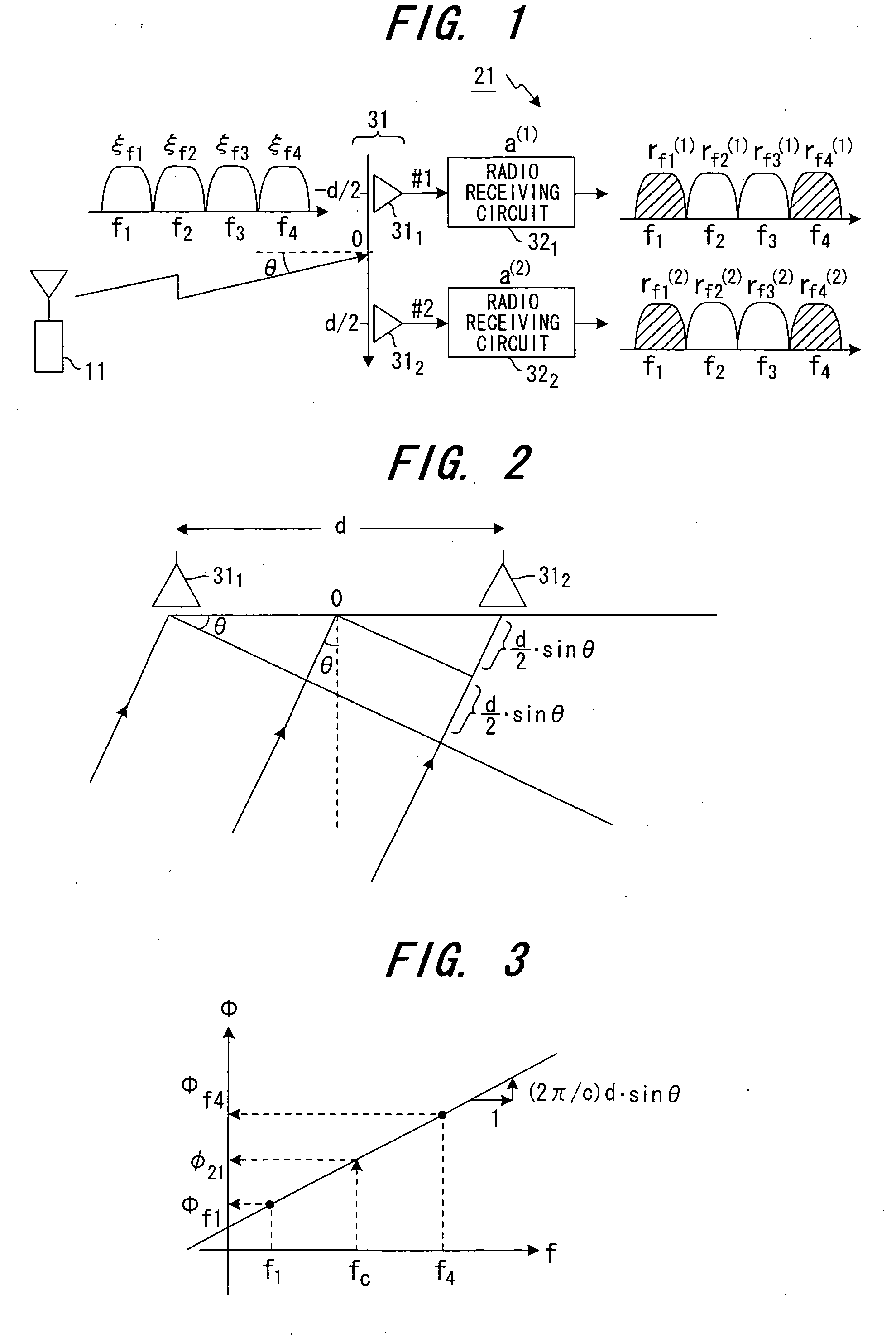
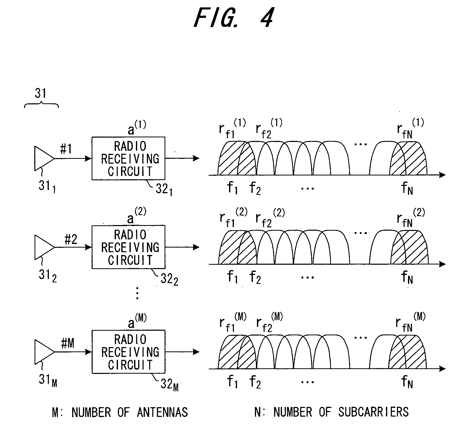
[0056] The mobile station 11 wirelessly transmits a multicarrier signal of frequencies f1 to fN. The radio waves (beams) of this radio signal impinge upon the linear array antenna (where the number of antennas is M) 31 of the base station 21 at an angle θ. Antennas 311 to 31M of the array antenna input the received signal to radio receiving circuits 321 to 32M, respectively. The radio receiving circuits 321 to 32M amplify the respective radio signals, subject the radio signals to frequency down-conversion processing and AD conversion processing and output baseband signals of the combined N-number of carriers. Narrow-band-signal extracting units 331 to 33M respectively separate and output signal components rf1(1) to rfN(1); r...

second embodiment

[0063] (C) Second Embodiment

[0064]FIG. 6 is a diagram illustrating the structure of a radio receiving apparatus according to a second embodiment of the present invention. Components identical with those of FIGS. 1 and 4 are designated by like reference characters.

[0065] The mobile station 11 wirelessly transmits a multicarrier signal of frequencies f1 to fN. The radio waves (beams) of this radio signal impinge upon the linear array antenna (where the number of antennas is M) 31 of the base station 21 at an angle θ. The antennas 311 to 31M of the array antenna input the received signals to the radio receiving circuits 321 to 32M, respectively. The radio receiving circuits 321 to 32M amplify the radio signals, subject the radio signals to frequency down-conversion processing and AD conversion processing and output baseband signals of the combined N-number of carriers. Narrow-band-signal extracting units 411 to 41M respectively separate and output the signal components rf1(1), rfN(1);...

third embodiment

[0081] (E) Third Embodiment

[0082] The foregoing embodiments relate to a case where a correction is applied upon estimating one of the phase-shift amounts φ(1) to φ(M) per each of the radio receiving circuits 321 to 32M. However, there are instances where in wide-band transmission such as OFDM transmission, the radio receiving circuits 321 to 32M have frequency characteristics and the phase-shift amounts θ fluctuate from one frequency band to another. In such cases it is necessary to obtain and correct the amount of phase shift on a per-frequency-band basis.

[0083]FIG. 12 is a diagram useful in describing the principles of a third embodiment of the present invention. Here OFDM subcarriers f1 to fN are partitioned into F-number of bands B1 to BF. In the case of OFDM, the number N of subcarriers is 128, 256, 512, etc.

[0084] The phase-variation & arrival-direction estimating unit 34 obtains phase-shift amounts φ(1)[1] to φ(M)[1]; φ(1)[2] to φ(M)[2]; . . . ; φ(1)[F] to φ(M)[F] in respec...


PUM


Abstract

Disclosed is a wireless communication apparatus having an array antenna constituted by a plurality of antennas, radio receiving circuits, which are provided for respective ones of the antennas, for amplifying respective ones of antenna receive signals and applying a frequency conversion to the baseband signals, and a demodulator for demodulating receive data from the baseband signals. A narrow-band-signal extracting unit extracts two narrow-band signals, which have the maximum frequency spacing between them, from the baseband signals of each of the antennas, an estimating unit estimates phase variation in each radio receiving circuit using the two narrow-band signals of each antenna, and a phase-variation correcting unit corrects for phase variation in each radio receiving circuit. The estimating unit estimates the direction of signal arrival using narrow-band signals of at least two antennas, a beam former applies receive beam-forming processing to each corrected signal based upon the direction of signal arrival, and a receive-signal processor demodulates receive data from the receive signal that has undergone beam-forming processing.

Description

BACKGROUND OF THE INVENTION [0001] This invention relates to a wireless communication apparatus and to a method of correcting for phase variation. More particularly, the invention relates to a wireless communication apparatus having an array antenna constituted by a plurality of antennas, a radio receiving circuit, which is provided for every antenna, for amplifying each antenna receive signal and subjecting baseband signals thereof to a frequency conversion, and a demodulator for demodulating receive data from the baseband signals, and to a method of correcting for phase variation in this apparatus. [0002] A CDMA scheme in a digital cellular wireless communication system using DS-CDMA techniques assigns channels by code so that communication may be performed simultaneously on these channels. However, signals from other communicating channels interfere and, as a result, there is a limit on the number of channels that can communicate simultaneously, i.e., there is a limit on channel ...

Claims


Application Information

Patent Timeline
Patent Type & Authority Applications(United States)
IPC IPC(8): H04M1/00
CPCH04B7/086H04B7/084
Inventor TSUTSUI, MASAFUMI
Owner FUJITSU LTD
Why Eureka
Try Eureka