Retainer device for mitral valve leaflets

a technology of mitral valve leaflets and retraction devices, which is applied in the field of treatment of mitral valve regurgitation, can solve the problems of distorting the shape of the mitral valve, reducing the ejection volume and reducing the size of the left ventricle to compensate with a larger stroke volume, so as to reduce the regurgitation of blood

Inactive Publication Date: 2006-12-28
MEDTRONIC VASCULAR INC
View PDF16 Cites 252 Cited by
  • Summary
  • Abstract
  • Description
  • Claims
  • Application Information

AI Technical Summary

Benefits of technology

This patent describes a new way to fix problems with the heart's mitrial valve that can cause serious health issues. It involves inserting a special tool called a holding device into a patient's body and then deploying it to keep the valve closed during treatment. This helps improve outcomes by reducing damage caused by excessive bleeding.

Problems solved by technology

The technical problem addressed in this patent text relates to finding a better way to treat mitrial valve regurgitation without damaging the leaflets or requiring complicated surgeries. Current approaches involve inserting a device into the coronary sinus or puncturing the leaflets with a metal clip or sutures, leading to possible complications like inflammation or blockages. There is also a risk of permanently altering the function of the valve if too much force is applied. Therefore, there is a desire for a new technique that can address this issue more effectively while avoiding harmful effects on the patient.

Method used


Image

  • Retainer device for mitral valve leaflets
  • Retainer device for mitral valve leaflets
  • Retainer device for mitral valve leaflets

Examples


Embodiment Construction

[0022] Throughout this specification, like numbers refer to like structures.

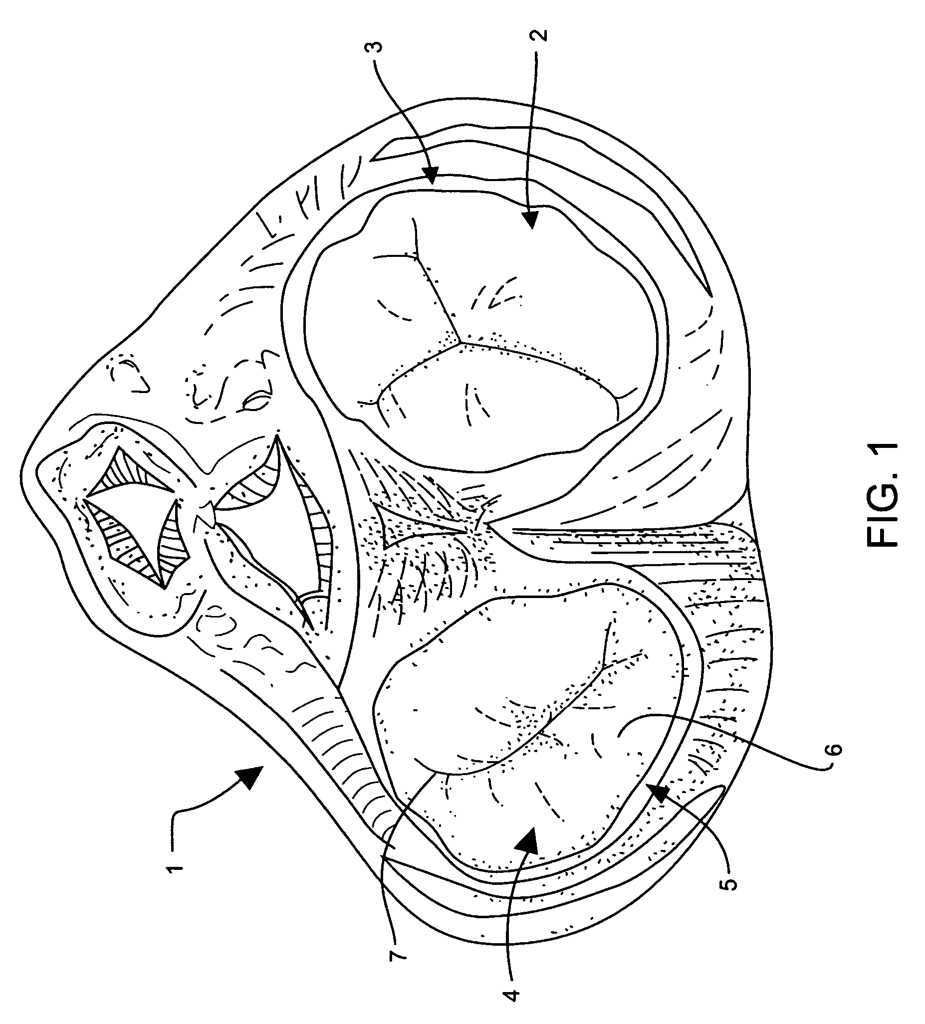
[0023] Referring to the drawings, FIG. 1 shows a cross-sectional view of heart 1 having tricuspid valve 2 and tricuspid valve annulus 3. Mitral valve 4 is adjacent mitral valve annulus 5. Mitral valve 4 is a bicuspid valve having anterior cusp 7 and posterior cusp 6. Anterior cusp 7 and posterior cusp 6 are often referred to, respectively, as the anterior and posterior leaflets.

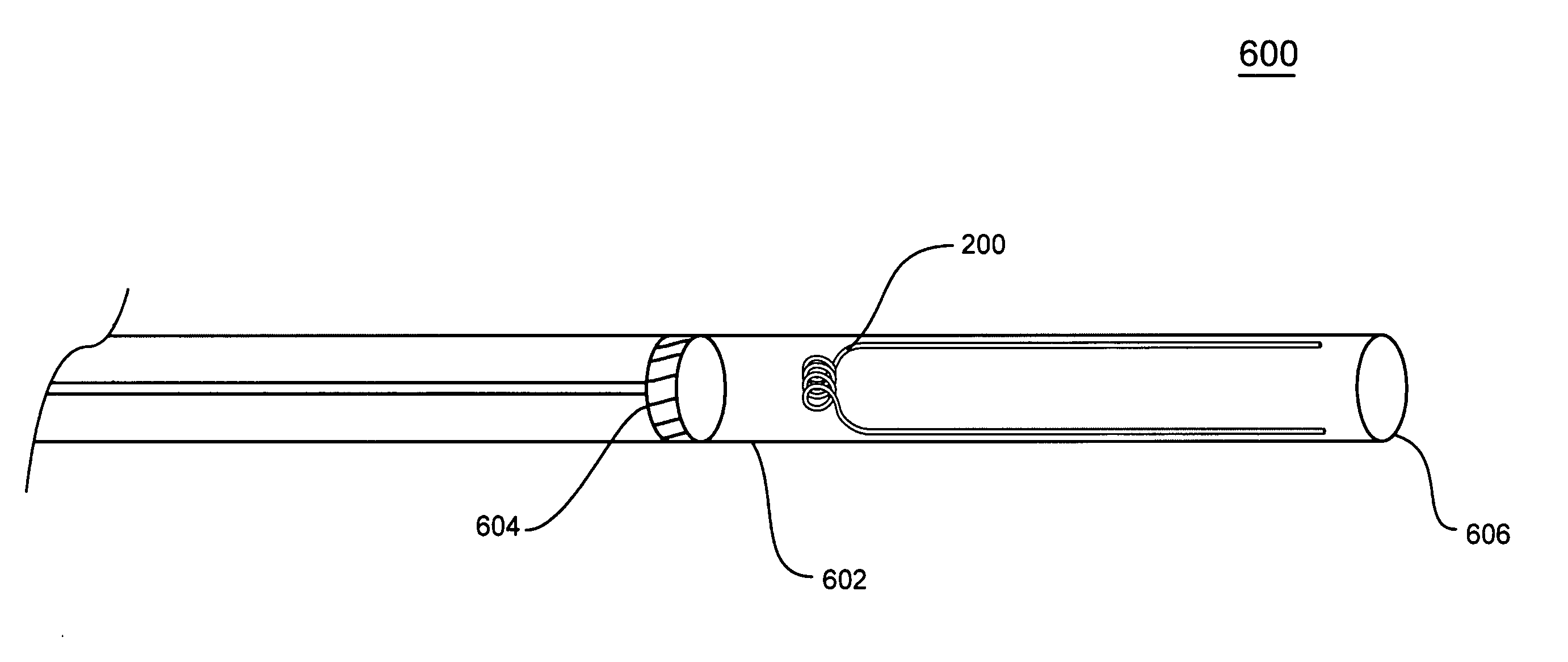
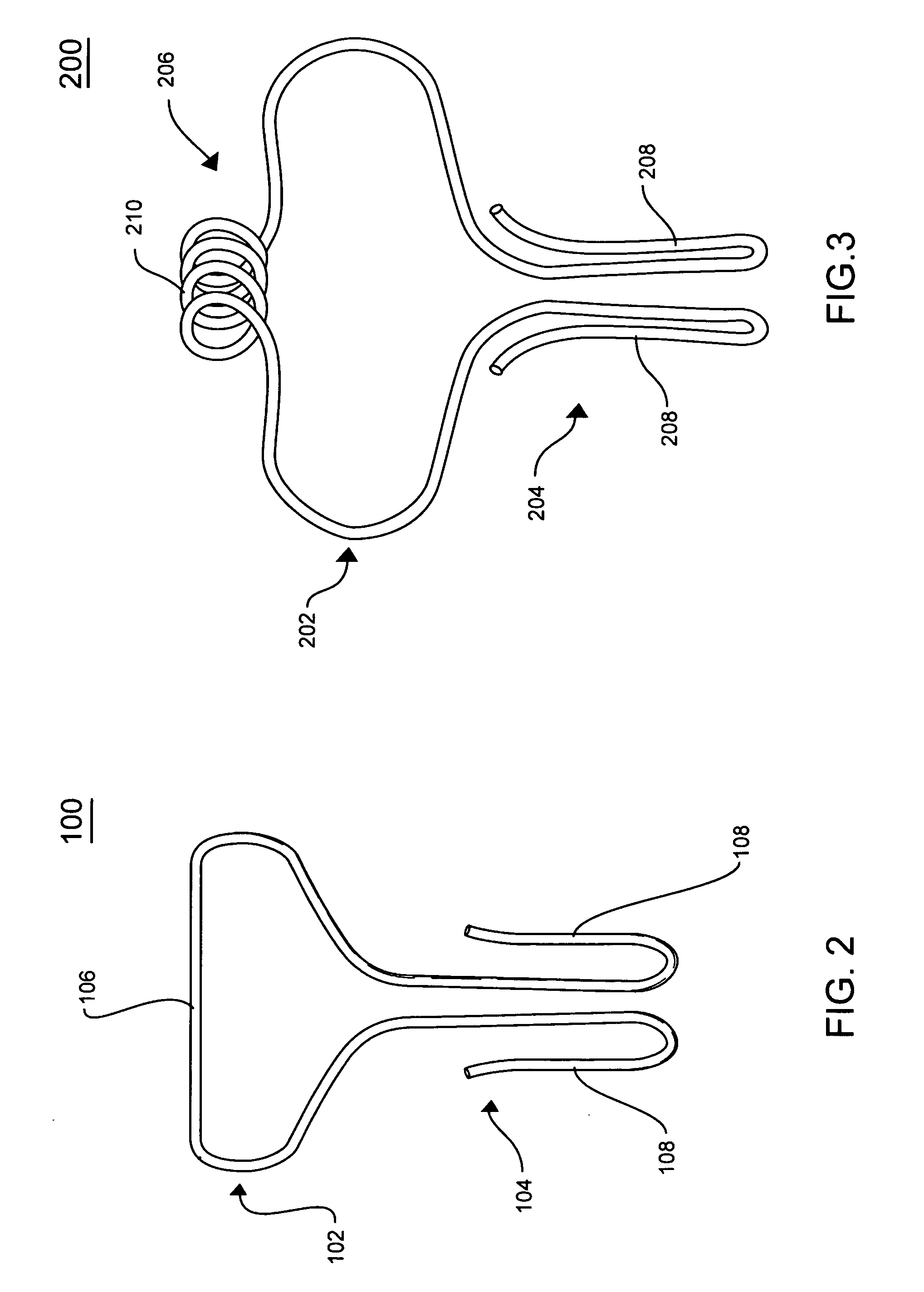
[0024]FIG. 2 portrays a holding device 100 for treating mitral valve regurgitation. Holding device 100 includes central anchoring portion 102, and at least two arm portions 104 extending from anchoring portion 102. Central anchoring portion 102 is circular or elliptical in shape, and has top portion 106 that is of a size so that when device 100 is placed adjacent to mitral valve 4, anchoring portion 102 will lodge against mitral valve annulus 5, and hold device 100 in place. Holding device 100 may be positioned so that when anchorin...


PUM


Abstract

A holding device for treating mitral valve regurgitation includes an anchoring portion and flexible arm portions. Upon deployment in the mitral valve, the arm portions assume a hook-shaped configuration and hold the leaflets in proximity to each other. One embodiment of the invention includes a method for preloading the holding device in a delivery catheter and deploying the device through the transverse axis of the mitral valve, allowing the arm portions of the holding device to grasp the mitral valve leaflets and hold them in proximity to each other, and thereby reduce both the cross sectional area of the mitral valve and regurgitation of blood through the valve.

Description


Claims


Application Information

Patent Timeline
Owner MEDTRONIC VASCULAR INC
Why Eureka
Try Eureka