Corrective artificial disc

a technology of artificial discs and discs, applied in the field of artificial discs, can solve the problems of reducing the motion and flexibility of the spine, accelerating the degeneration of the disc, and fusing adjacent vertebrae into a single bone mass,

Inactive Publication Date: 2006-12-28
LANX INC
View PDF23 Cites 237 Cited by
  • Summary
  • Abstract
  • Description
  • Claims
  • Application Information

AI Technical Summary

Benefits of technology

[0012] The foregoing and other features, utilities and advantages of the invention will be apparent from the followin

Problems solved by technology

While fusing the vertebrae into one solid piece of bone is the conventional practice, fusing adjacent vertebrae into a single bone mass is a less than ideal solution.
In particular, fusing two or more vertebrae into a single bone mass causes additional stress on the remaining vertebrae and discs accelerating any potential degeneration.
Moreover, the fused bone mass may lead to decreased motion and flexibility in the spine.
The Beer et al. device is less than satisfactory because the coiled springs can be damaged and lose their elasticity over time.
Further, the coiled springs provide limited shock absorption requiring the use of a compressible pouch of biocompatible material to provide additional shock absorption.
Moreover, adjacent vertebrae need significant separation to allow for insertion of the prosthetic device potentially causing trauma to the surrounding structures.
The Ratron device is relatively impractical, however, because the plac

Method used


Image

  • Corrective artificial disc
  • Corrective artificial disc
  • Corrective artificial disc

Examples


Embodiment Construction

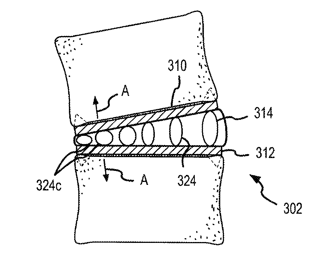
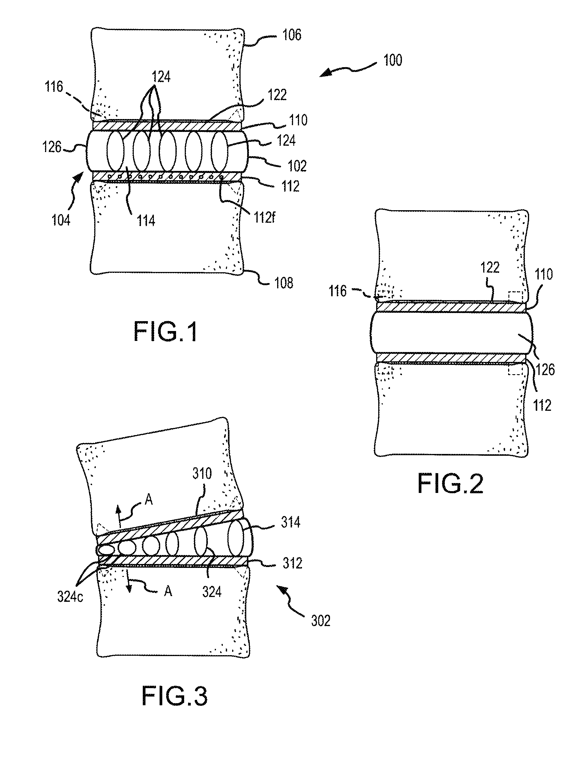
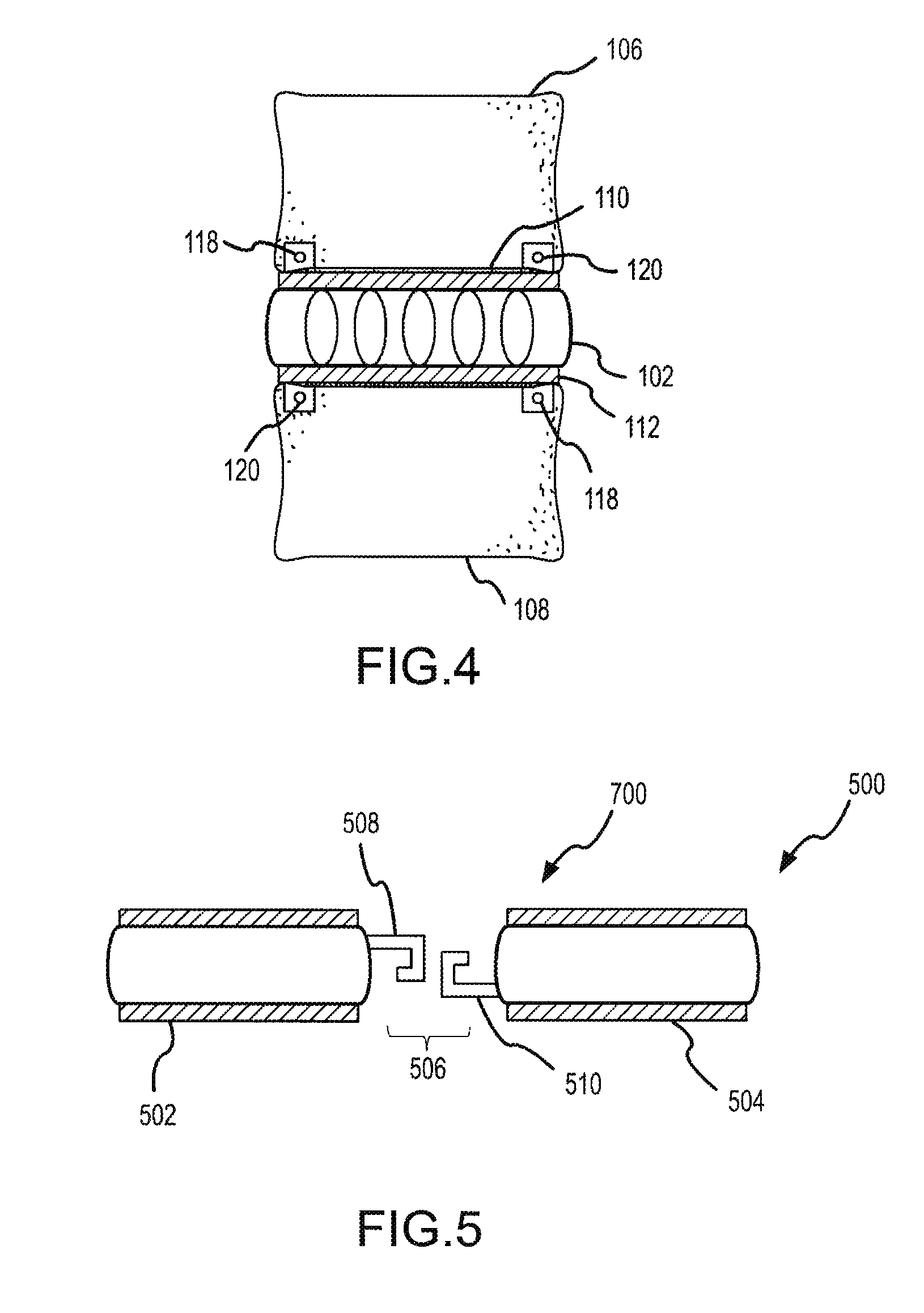
[0025] Some embodiments of the present invention are described with reference to FIGS. 1 to 11. FIGS. 1-11 generally show the present invention on an eye level, off the shelf view with fixation spikes in phantom. One of skill in the art, on reading the below disclosure, will recognize that the exact configuration of the present invention will depend, in part, on the anatomy of the patient.

[0026] In particular, FIG. 1 shows a cross section of an anterior view of a portion of a spinal column 100 with an artificial disc 102. FIG. 2 shows a lateral, elevation view of spinal column 100 with artificial disc 102. Disc 102 is implanted in an intervertebral space 104 situated between a superior vertebral body 106 and an inferior vertebral body 108. Disc 102 includes a superior endplate 110, an inferior endplate 112, and a core 114. Superior endplate 110 and inferior endplate 112 may be formed of a biocompatible metal including shaped memory alloys, other metallic alloys, PEEK, resorbable, p...


PUM


Abstract

An artificial disc is provided having a rigid pre-formed phase. The disc is implanted in an elastic phase and activated to the pre-formed phase. The pre-formed shape provides corrective forces to stabilize or correct spinal abnormalities.

Description

RELATED APPLICATIONS [0001] This application is a continuation in part application of U.S. patent application Ser. No. 10 / 641,530, titled SHPAED MEMORY ARTIFICIAL DISC AND METHODS OF ENGRAFTING THE SAME, filed Aug. 14, 2003, which claims the benefit of U.S. Provisional Patent Application 60 / 404,481, filed Aug. 19, 2002, titled SHAPE MEMORY ARTIFICIAL DISC.FIELD OF THE INVENTION [0002] The present invention relates to artificial intervertebral discs and, more particularly, artificial intervertebral discs constructed from shaped memory alloys that can be used to correct spinal abnormalities. BACKGROUND OF THE INVENTION [0003] The vertebrae of the human spine are arranged in a column with one vertebra on top of the next. Between adjacent vertebrae exists an intervertebral disc that transmits force between adjacent vertebrae and provides a cushion between the adjacent vertebrae. [0004] The spine can suffer from many degenerations, diseases, and deformities that can cause back pain (here...

Claims


Application Information

Patent Timeline
IPC IPC(8): A61F2/44
CPCA61F2/0077A61F2250/0009A61F2/30767A61F2/442A61F2002/30093A61F2002/30329A61F2002/30556A61F2002/30565A61F2002/30566A61F2002/30578A61F2002/30841A61F2002/4435A61F2002/444A61F2002/448A61F2210/0019A61F2220/0025A61F2/30742A61F2002/30092
Inventor THRAMANN, JEFFERY
Owner LANX INC
Why Eureka
Try Eureka