Corrugated metal plate bridge with composite concrete structure

a corrugated metal plate and concrete technology, applied in the direction of bridge materials, arch-type bridges, constructions, etc., can solve the problem of less than desirable use of unsightly or cumbersome bridge structures

Inactive Publication Date: 2007-01-04
AIL INT
View PDF20 Cites 29 Cited by
  • Summary
  • Abstract
  • Description
  • Claims
  • Application Information

AI Technical Summary

Problems solved by technology

It can be appreciated that in these environments, the use of an unsightly or cumbersome bridge structure is less than desirable.

Method used


Image

  • Corrugated metal plate bridge with composite concrete structure
  • Corrugated metal plate bridge with composite concrete structure
  • Corrugated metal plate bridge with composite concrete structure

Examples


Embodiment Construction

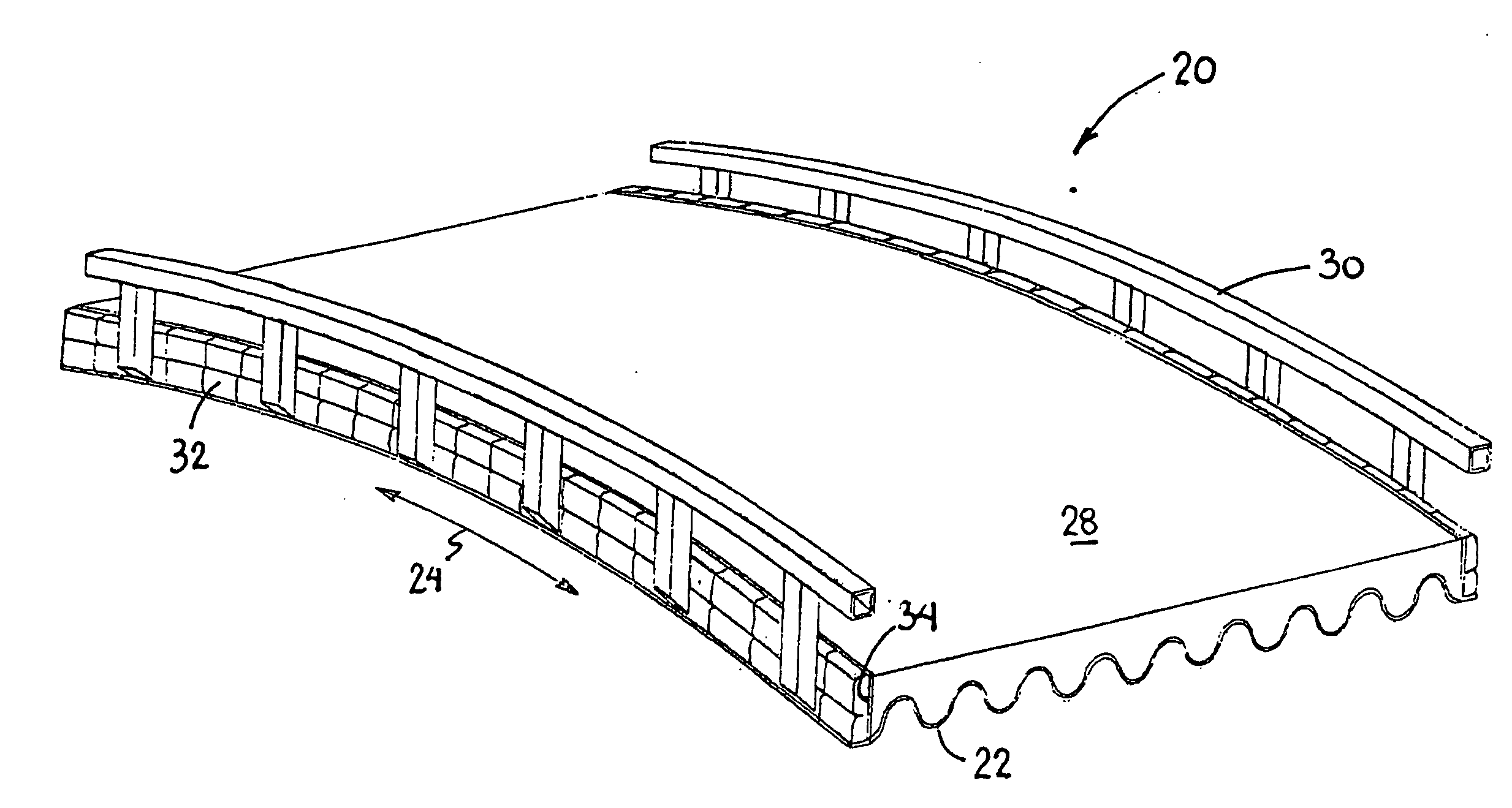
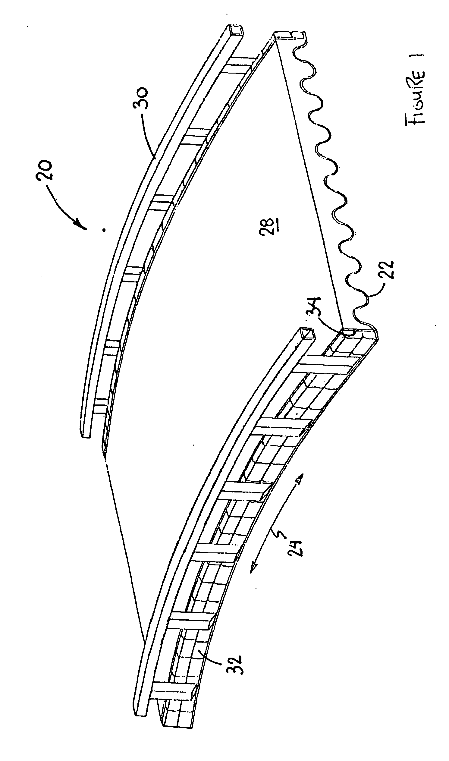
[0022] In accordance with this invention, a light to medium-duty bridge structure for spanning water courses and the like of up to 50 feet (or approximately 15 m) across is provided. The bridge structure described below is particularly suited for use in golf courses, or in other similar settings requiring a light to medium-duty bridge structure. Although very well suited for new installations, the bridge structure is also suitable as a replacement bridge in existing areas. Each of the structural members that comprise the bridge structure are light-weight and easily managed, permitting easier transport of the disassembled structure to the desired location. Once assembled, the resultant bridge structure, with the integrated concrete support / running surface provides a composite bridge structure, capable of withstanding light to medium-duty loads (i.e. pedestrian traffic, golf carts, small tractors, etc).

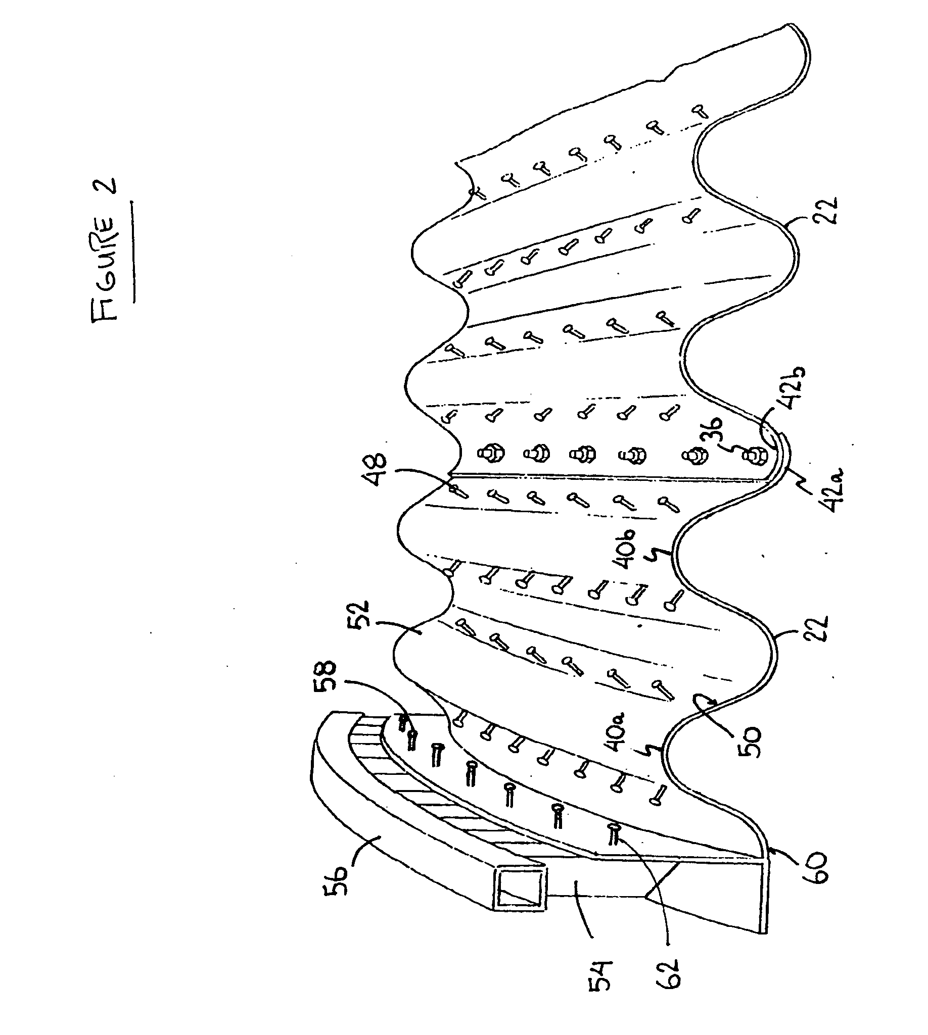
[0023] The bridge structure is generally comprised of corrugated metal plate with ...


PUM


Abstract

A light to medium-duty bridge structure suitable for use in golf-courses, parks and similar settings. The bridge structure comprises at least one corrugated metal plate having corrugations oriented parallel to the longitudinal axis of the bridge structure. Applied to the upper surface of this corrugated metal plate is a layer of concrete or like material to provide a support/running surface. The corrugated metal plate is provided with a plurality of devices adapted to engage the concrete or like material so as to provide a composite corrugated metal plate-concrete structure capable of supporting light to medium-duty loads.

Description

FIELD OF THE INVENTION [0001] This invention relates to a light to medium-duty bridge comprising a composite corrugated metal plate / concrete structure. BACKGROUND OF THE INVENTION [0002] Golf courses, parks and other similarly landscaped environments often require bridge structures to span water courses, pedestrian walkways or other obstructions. It can be appreciated that in these environments, the use of an unsightly or cumbersome bridge structure is less than desirable. Light to medium-duty bridge structures are particularly suited for these applications. [0003] Typically, light duty bridge structures employ structural members such as I-beams to provide the required span. The I-beams serve to support an upper support surface, which may further comprise a concrete or asphalt running surface. An example of this structure is shown in U.S. Pat. No. 501,534 to Palmer. Another lightweight bridge structure is shown in U.S. Pat. No. 3,768,108 to Wadsworth, which provides a pair of arched...

Claims


Application Information

Patent Timeline
Patent Type & Authority Applications(United States)
IPC IPC(8): E01D19/12
CPCE01D19/125E01D2101/268E01D2/04E01D19/12
Inventor WILSON, MICHAEL W.
Owner AIL INT
Why Eureka
Try Eureka