
Girder bridge protection device usin sacrifice means

a protection device and bridge technology, applied in the direction of bridges, bridge structural details, shockproofing, etc., can solve the problems of inability to resist seismic behavior in the direction of the bridge axis, inability to dissipate energy, and difficult to gain access to the internal shear keys after installation, so as to improve the structural behavior of main parts and effectively dissipate energy generated

Inactive Publication Date: 2007-01-04
IND ACADEMIC CORP FOUND YONSEI UNIV
View PDF9 Cites 15 Cited by
  • Summary
  • Abstract
  • Description
  • Claims
  • Application Information

AI Technical Summary

Benefits of technology

[0035] In particular, an object of the present invention is to advantageously modify the subject matters of Korean Patent Laid-open Publication No. 2004-97591 and provide an girder bridge protection device using sacrifice means which includes a symmetrical main support member playing a role of improving the structural behavior of main parts while an earthquake does not occur and of effectively dissipating energy generated by a seismic load when an earthquake occurs.
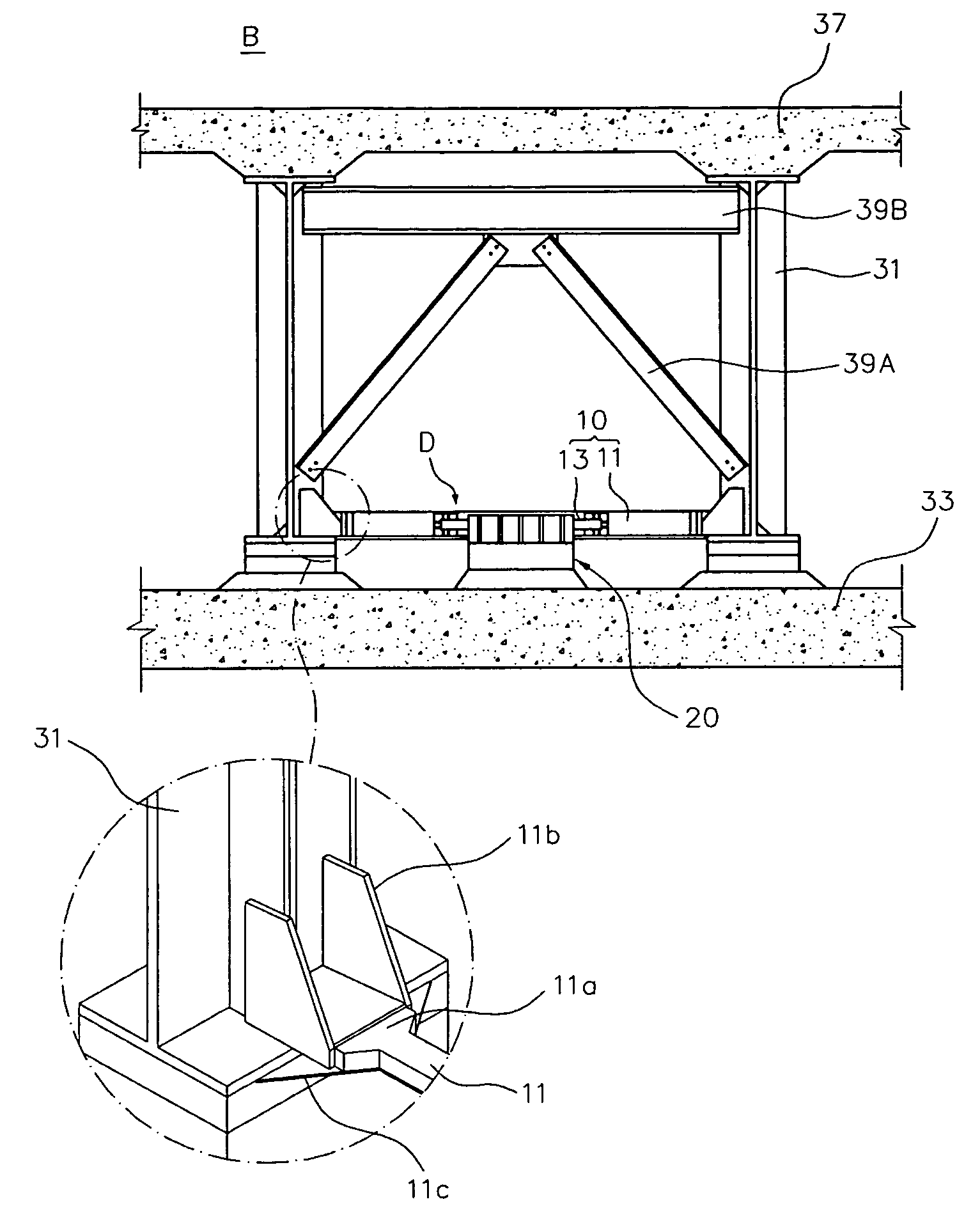
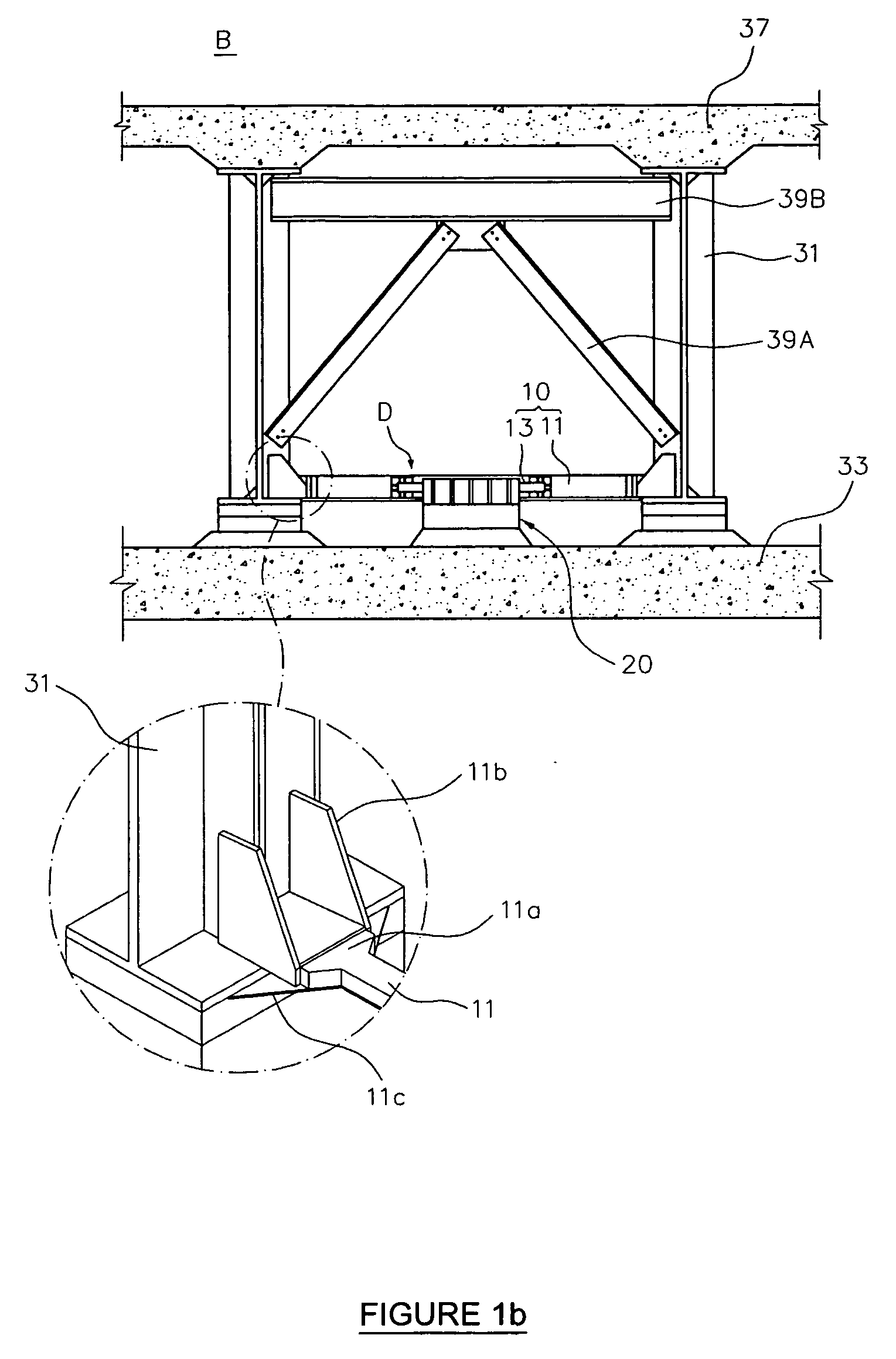
[0036] In order to achieve the above object, according to the present invention, there is provided an girder bridge protection device comprising sacrifice means including girders which are installed on an upper surface of a bridge seat of an abutment or pier to support a bridge floor, a symmetrical main support member which connects two girders and has a pipe-shaped configuration, and an auxiliary support member which projects from one surface of a center portion of the main support member in a direction perpendicular to an axial direction of the main support member; and restraining means secured to the bridge seat of the abutment or pier and including an accommodating section which accommodates the auxiliary support member such that the auxiliary support member is separated from the accommodating section in a forward and rearward direction and in a leftward and rightward direction, thereby controlling behavior of the auxiliary support member.

Problems solved by technology

In the case of the internal shear keys, while advantages are provided in that it is possible to resist seismic behavior both in the direction of the bridge axis and in the direction perpendicular to the bridge axis, disadvantages are also provided in that it is not easy to gain access to the internal shear keys after installation.
In the case of the external shear keys, while advantages are provided in that it is easy to gain access to the external shear keys, disadvantages are provided in that it is impossible to resist seismic behavior in the direction of the bridge axis.
However, these devices are applied on the assumption that the deformation or load generated in the direction of the bridge axis is restrained in some way, and therefore, suffer from defects in that they are incapable of dissipating energy and preventing displacement generated in the direction of the bridge axis due to a seismic load (Zahrai et al., 1999; and Bruneau et al., 2002).
As a result, the conventional girder bridge protection devices as mentioned above encounter problems as described below.
First, it is difficult to apply the conventional girder bridge protection devices to existing bridges and newly constructed bridges, traffic control is necessary to construct the conventional girder bridge protection devices, and it is essential to use costly equipment which is specially fabricated, whereby the economic burden increases.
Second, since the conventional girder bridge protection devices do not normally play a specific role with regard to the behavior of a bridge, if an earthquake does not occur throughout the lifetime of the bridge, the conventional girder bridge protection devices cannot perform any function, whereby economic loss is caused.
Third, it is impossible for the conventional girder bridge protection devices to resist a seismic load in all directions including the direction of the bridge axis and the direction perpendicular to the bridge axis.
Fourth, since it is impossible to precisely predict elastic and plastic behavior of sacrifice means, it is difficult to secure structural stability.
Fifth, maintenance and repair work cannot be easily implemented for the conventional girder bridge protection devices.
Further, when the sacrifice means is damaged, it is not easy to replace the damaged sacrifice means with new one.
Nevertheless, the sacrifice bracing cannot properly resist a seismic shock which acts in the direction perpendicular to the bridge axis.

Method used


Image

  • Girder bridge protection device usin sacrifice means
  • Girder bridge protection device usin sacrifice means
  • Girder bridge protection device usin sacrifice means

Examples


Embodiment Construction

[0046] Reference will now be made in greater detail to a preferred embodiment of the invention, an example of which is illustrated in the accompanying drawings. Wherever possible, the same reference numerals will be used throughout the drawings and the description to refer to the same or like parts.

[0047] In the drawings, the same reference numerals, in particular the reference numerals having the same first and second figures or the same first and second figures and the same reference letters designate members having the same function. In this regard, it is to be noted that the component parts indicated by respective reference numerals conform to this rule unless specifically mentioned.

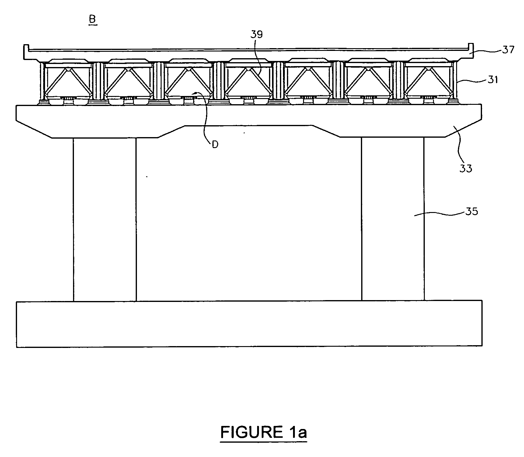
[0048] In explaining an girder bridge protection device D according to the present invention, directions are set as follows with reference to FIGS. 1a and 1b. A lengthwise direction of a super structure which connects piers positioned at both ends of a bridge B, that is, the direction of a bridge a...


PUM


Abstract

An girder bridge protection device comprises sacrifice means including girders which are installed on an upper surface of a bridge seat of an abutment or pier to support a bridge floor, a symmetrical main support member which connects two girders and has a pipe-shaped configuration, and an auxiliary support member which projects from one surface of a center portion of the main support member in a direction perpendicular to an axial direction of the main support member; and restraining means secured to the bridge seat of the abutment or pier and including an accommodating section which accommodates the auxiliary support member such that the auxiliary support member is separated from the accommodating section in a forward and rearward direction and in a leftward and rightward direction, thereby controlling the behavior of the auxiliary support member.

Description

BACKGROUND OF THE INVENTION [0001] 1. Field of the Invention [0002] The present invention relates, in general, to a device for protecting a bridge, and, more particularly, to an girder bridge protection device using sacrifice means which functions to support loads normally applied to a bridge and to dissipate energy through plastic behavior caused by sacrificing a symmetrically structured main support member when a seismic load is applied, thereby protecting the remaining main parts of the bridge. [0003] 2. Description of the Prior Art [0004] In the present specification, sacrifice means is a member implementing the concept of a passive energy dissipation device. The member serves as a secondary element which plays a structural role while an earthquake does not occur. When a seismic load is applied, the member plays a role of passively dissipating energy generated in a structure and thereby improving girder performance. [0005] Conventional techniques associated with a passive energy...

Claims


Application Information

Patent Timeline
IPC IPC(8): E01D1/00
CPCE01D19/00E01D19/04E04H9/021
Inventor KIM, SANG-HYO
Owner IND ACADEMIC CORP FOUND YONSEI UNIV
Learn More