Hydrogen fuel supply system

a technology of hydrogen fuel supply and hydrogen fuel, which is applied in the direction of electrochemical generators, machines/engines, mechanical equipment, etc., can solve the problems of difficult storage, high cost of hydrogen acquisition, and the inability to use reaction equipment in industrial equipment, such as hydrogen internal combustion engines or hydrogen power generators, to achieve the effect of quick supply

Inactive Publication Date: 2007-01-04
WANG HSU YANG
View PDF5 Cites 19 Cited by
  • Summary
  • Abstract
  • Description
  • Claims
  • Application Information

AI Technical Summary

Benefits of technology

This patent describes a new way to produce hydrogen gas for use in vehicles that run on this energy source. It involves separating out small amounts of methanol from water and converting them into hydrogen through a process called micromixing. With the help of a special refrigerant, the resultant hydrogen can then be quickly sent to either an engine or generator for use there. Overall, this technology allows for more efficient production of clean hydrogen gas.

Problems solved by technology

The technical problem addressed in this patent text is the difficulty and high cost of storing and obtaining hydrogen, which is necessary for its use as an energy source. The text describes a method for obtaining hydrogen from methanol, but the reaction is not currently utilized in industrial equipment due to certain technological obstacles.

Method used


Image

  • Hydrogen fuel supply system
  • Hydrogen fuel supply system
  • Hydrogen fuel supply system

Examples


example 1

[0081] (A) The feed speed of methanol aqueous solution: 70 g / min. [0082] (B) The inlet speed of air: 24.49 g / min. [0083] (C) Ratio of molecular number of water / methanol: 0.8 [0084] (D) Temperature of catalyst steam reactor: 480° C.

[0085] Test result: By measurement of Gas Chromatograph and Float type flow meter, 64% of H2, 23% of CO2 and 12% of N2 are obtained. The production rate of Hydrogen is 8 g / min.

example 2

[0086] (A) The feed speed of methanol aqueous solution: 140 g / min. [0087] (B) The inlet speed of air: 52.6 g / min. [0088] (C) Ratio of molecular number of water / methanol: 0.75 [0089] (D) Temperature of catalyst steam reactor: 440° C.

[0090] Test result: By measurement of Gas Chromatograph and Float type flow meter, 64.5% of H2, 23.3% of CO2 and 11.6% of N2 are obtained. The production rate of Hydrogen is 17 g / min.

example 3

[0091] (A) The feed speed of methanol aqueous solution: 200 g / min. [0092] (B) The inlet speed of air: 132.3 g / min. [0093] (C) Ratio of molecular number of water / methanol: 0.6 [0094] (D) Temperature of catalyst steam reactor: 330° C.

[0095] Test result: By measurement of Gas Chromatograph and Float type flow meter, 59% of H2, 22.3% of CO2 and 18.1% of N2 are obtained. The production rate of Hydrogen is 25 g / min.


PUM


Abstract

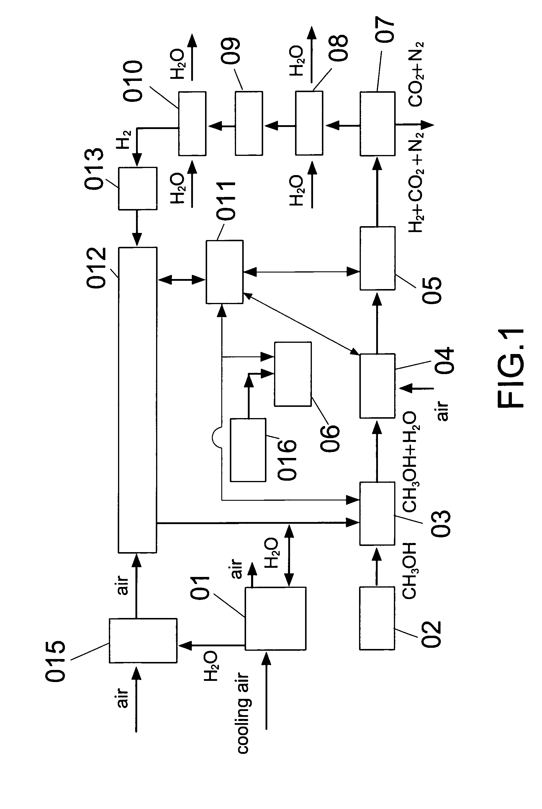
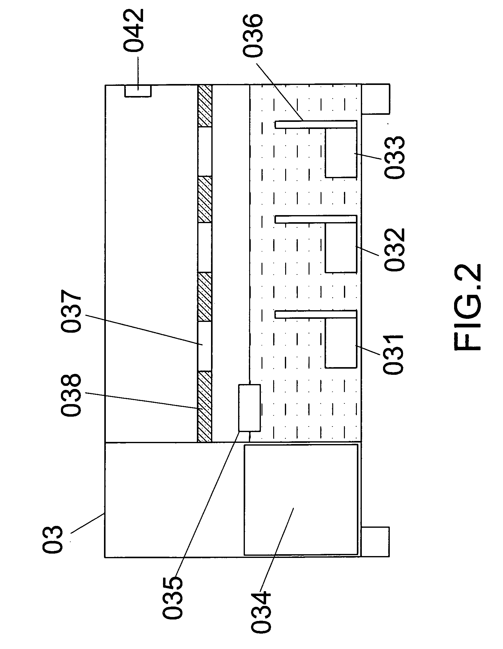
A hydrogen fuel supply system comprising a methanol aqueous solution particulates generator, spark-plasma heater, catalytic reactor, hydrogen separation unit, hydro-evaporating cooler, hydrogen compressor, hydrogen injection system, etc. By properly mixing methanol and water to form a methanol aqueous solution, then vibrated by a methanol aqueous solution particulates generator to form micro to nano sized particulates of aqueous-methanol, and the micro to nano sized particulates is then heated in high temperature by a spark-plasma heater, then through a catalytic reactor to form a gaseous mixture of hydrogen, carbon dioxide, and nitrogen. Then the hydrogen is separated by a hydrogen separation unit. Finally, the hydrogen is chilled by a hydro-evaporation cooler and then compressed by a hydrogen compressor. The resulting hydrogen can be supplied to hydrogen internal-combustion engines or hydrogen power generators by hydrogen injection systems.

Description


Claims


Application Information

Patent Timeline
Owner WANG HSU YANG
Why Eureka
Try Eureka