
Speaker system and speaker enclosure

a speaker system and speaker technology, applied in the direction of transducer details, electrical transducers, electrical apparatus casings/cabinets/drawers, etc., can solve the problems of too high passing through the resonance pipe, affecting the sound quality of the speaker system, and reducing the bass boosting function remarkably

Active Publication Date: 2007-01-04
YAMAHA CORP
View PDF20 Cites 25 Cited by
  • Summary
  • Abstract
  • Description
  • Claims
  • Application Information

AI Technical Summary

Benefits of technology

[0007] In order to solve the foregoing problems, an object of the invention is to provide a speaker system and a speaker enclosure in which sufficiently boosted bass can be output though the size of the speaker system or speaker enclosure is small, and in which Q of vibration of a vibration plate can be increased while rolling or rocking can be prevented.
[0013] a sealing member that covers a gap formed between the vibration portion and a rim portion of the opening portion while enabling vibration of the vibration portion so as to keep the speaker enclosure airtight.
[0020] a sealing member that covers a gap formed between the vibration portion and a rim portion of the opening portion while enabling vibration of the vibration portion so as to keep the main body airtight.

Problems solved by technology

As a result, there is a problem that the bass boosting function is reduced remarkably because air resistance becomes too high.
Moreover, there is a problem that wind noise like a whistle is generated because the velocity of air passing through the resonance pipe becomes too high.
This contradicts the compliance.
Moreover, the heavy vibration plate hardly vibrates perfectly in parallel, so that the vibration of the heavy vibration plate is apt to involve abnormal variation called “rolling” or “rocking”.
The abnormal vibration brings increase in distortion and wasteful consumption of energy to thereby reduce efficiency.
For this reason, the edge needs to be strong, so that there is a problem that Q of vibration is reduced because of the damping effect of the edge.

Method used


Image

  • Speaker system and speaker enclosure
  • Speaker system and speaker enclosure
  • Speaker system and speaker enclosure

Examples


first embodiment

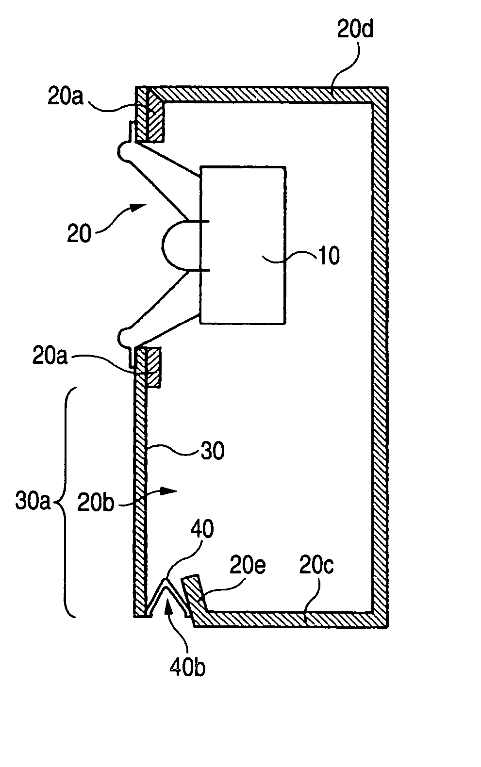
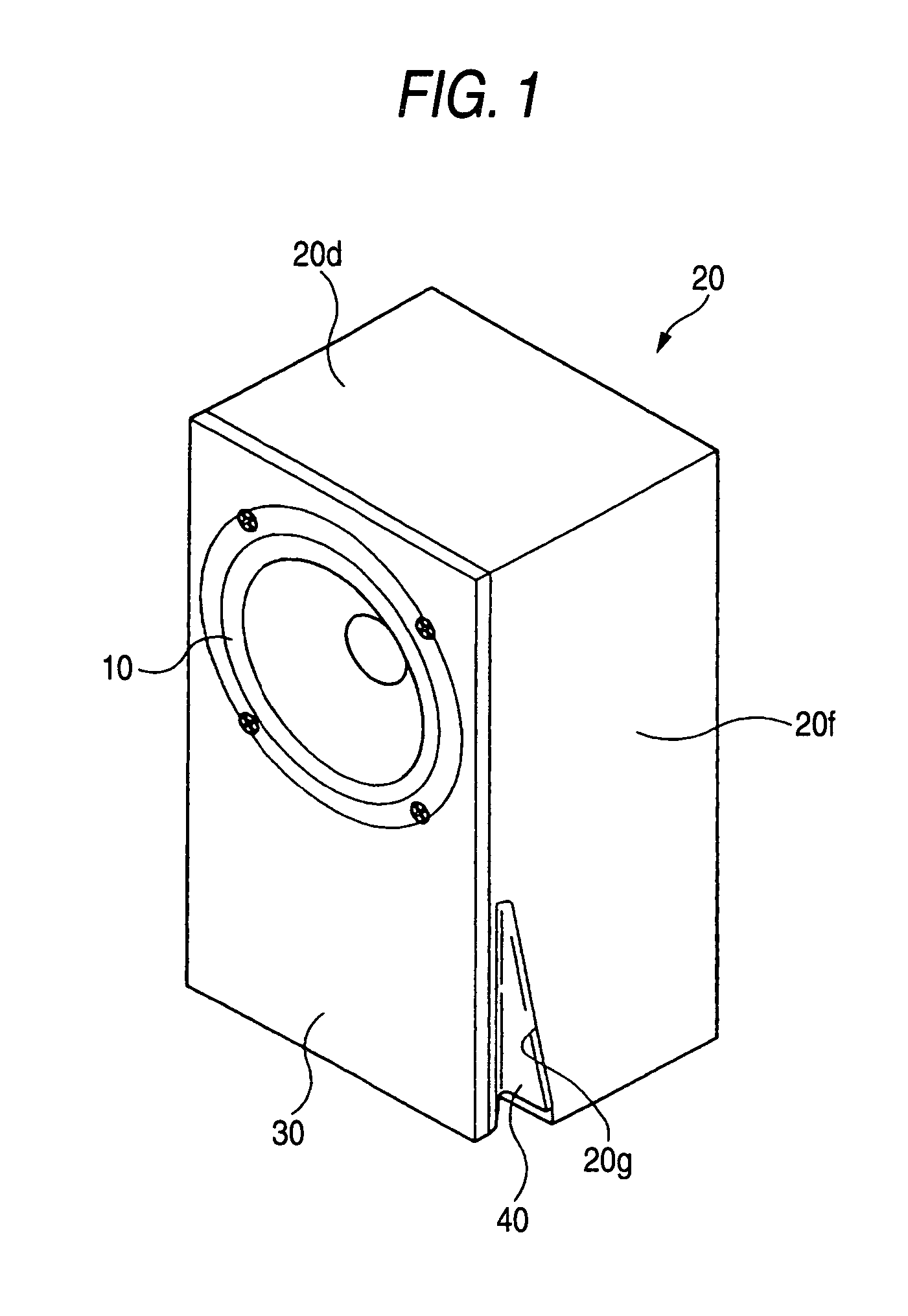
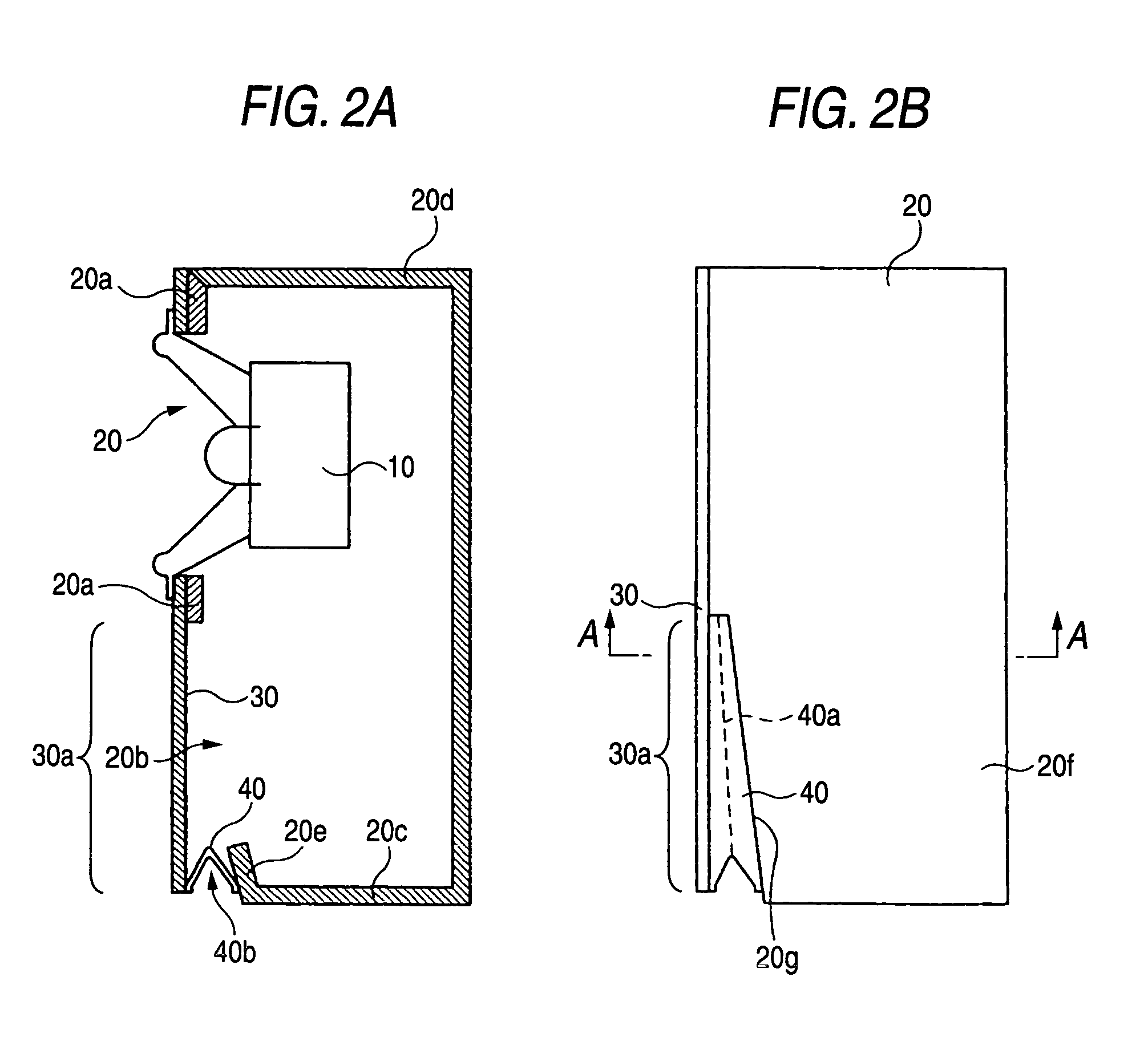
[0045]FIG. 1 is a perspective view showing external appearance of a speaker system according to a first embodiment of the invention. FIGS. 2A and 2B are a side sectional view and a side view showing the configuration of the speaker system according to this embodiment.

[0046] In FIG. 1, a speaker 10 having a voice coil, a magnet, etc. is mounted in a front surface of a speaker enclosure 20. The speaker enclosure 20 is a rectangular parallelepiped closed type enclosure which has six surfaces each made of a plate-like member (such as wood, synthetic resin, metal or plywood thereof).

[0047] As shown in FIG. 2A, a thin plate-like vibration plate 30 is attached to a baffle plate 20a in a front surface of the speaker enclosure 20. The vibration plate 30 is formed to have a size equal to the size of the front surface of the speaker enclosure 20 so that the front surface of the speaker enclosure 20 is entirely covered with the vibration plate 30. A speaker mount hole is provided so as to pie...

second embodiment

[0089] Next, a second embodiment of the invention will be described. FIG. 13 is a perspective view showing external appearance of the second embodiment of the invention. In FIG. 13, a speaker 10 is mounted in an upper portion of a baffle plate 50a in a front surface of a rectangular parallelepiped speaker enclosure 50. An opening portion 60 cut away as a narrow and long U-shaped portion is provided in a range of from a center portion of the baffle plate 50a to a lower portion of the baffle plate 50a.

[0090] In this case, the inner portion of the U-shaped portion serves as a vibration plate 51. That is, an upper portion of the vibration plate 51 is integrated with the baffle plate 50a while the other portion of the vibration plate 51 is separated from the baffle plate 50a by the U-shaped opening portion 60. Accordingly, the vibration plate 51 can vibrate freely in a state where the upper end of the vibration plate 51 is fixed.

[0091]FIGS. 14A and 14B are a side sectional view and a c...


PUM


Abstract

A speaker system, includes a speaker enclosure that has a surface, a speaker that is mounted in the speaker enclosure, a vibration portion that has one end fixed on the surface of the speaker enclosure so as to be allowed to vibrate elastically, an opening portion that is provided in the surface where the vibration portion is provided, and disposed in a position corresponding to a vibration region of the vibration portion and a sealing member that covers a gap formed between the vibration portion and a rim portion of the opening portion while enabling vibration of the vibration portion so as to keep the speaker enclosure airtight.

Description

BACKGROUND OF THE INVENTION [0001] The present invention relates to a technique for a speaker system and a speaker enclosure. [0002] Various types of speaker systems have been developed. For example, a bass reflex speaker system or a drawn cone speaker system is a representative of such speaker systems. [0003]“Bass reflex” is a technique for boosting bass by using Helmholtz resonance. “Drawn cone” is a technique for boosting bass by using resonance with air in the volume of an enclosure in which a speaker unit having no drive circuit is mounted. [0004] In “bass reflex”, a small-size and slender resonance pipe is required for reducing the resonance frequency if the volume of the enclosure is small. As a result, there is a problem that the bass boosting function is reduced remarkably because air resistance becomes too high. Moreover, there is a problem that wind noise like a whistle is generated because the velocity of air passing through the resonance pipe becomes too high. [0005] In...

Claims


Application Information

Patent Timeline
IPC IPC(8): H05K5/00
CPCH04R1/2888H04R1/2834
Inventor NORO, MASAOARAI, AKIRA
Owner YAMAHA CORP
Learn More