Packaging device and buffer

a packaging device and buffer technology, applied in packaging, sustainable manufacturing/processing, large containers, etc., can solve the problems of increasing plastic waste including waste of pet bottles, harmful substances can remain in burnt ashes after incineration, and the recycling ratio has not been so high

Inactive Publication Date: 2007-01-04
RICOH KK
View PDF7 Cites 5 Cited by
  • Summary
  • Abstract
  • Description
  • Claims
  • Application Information

AI Technical Summary

Benefits of technology

[0016] It is an object of the present invention to at least partially solve the problems in the conventional technology.

Problems solved by technology

On the other hand, a problem of the plastic waste including wasted PET-bottles is increasing.
That is, if the PET-bottles are incinerated as a waste, there is a possibility that harmful substances can remain in the burnt ashes after incineration.
However, the recycling ratio has not been so high, and when the material is finally disposed of as a waste, there is the same problem mentioned above.
However, washing and the like of the bottles are troublesome, and the current amount of reuse is not sufficient as a measure against the increasing amount of wasted PET-bottles.
Under such circumstances, articles are generally packaged by forming the buffer members so as to match the shape of the article to be transported, and under current circumstances, cost and time of investment for plant and equipment, and designing with respect to packaging materials are required for each article.
Furthermore, to perform such designing and control, types of the parts increase, and the parts control is complicated accordingly.

Method used


Image

  • Packaging device and buffer
  • Packaging device and buffer
  • Packaging device and buffer

Examples


first embodiment

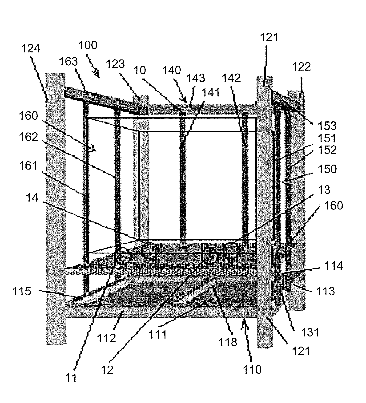
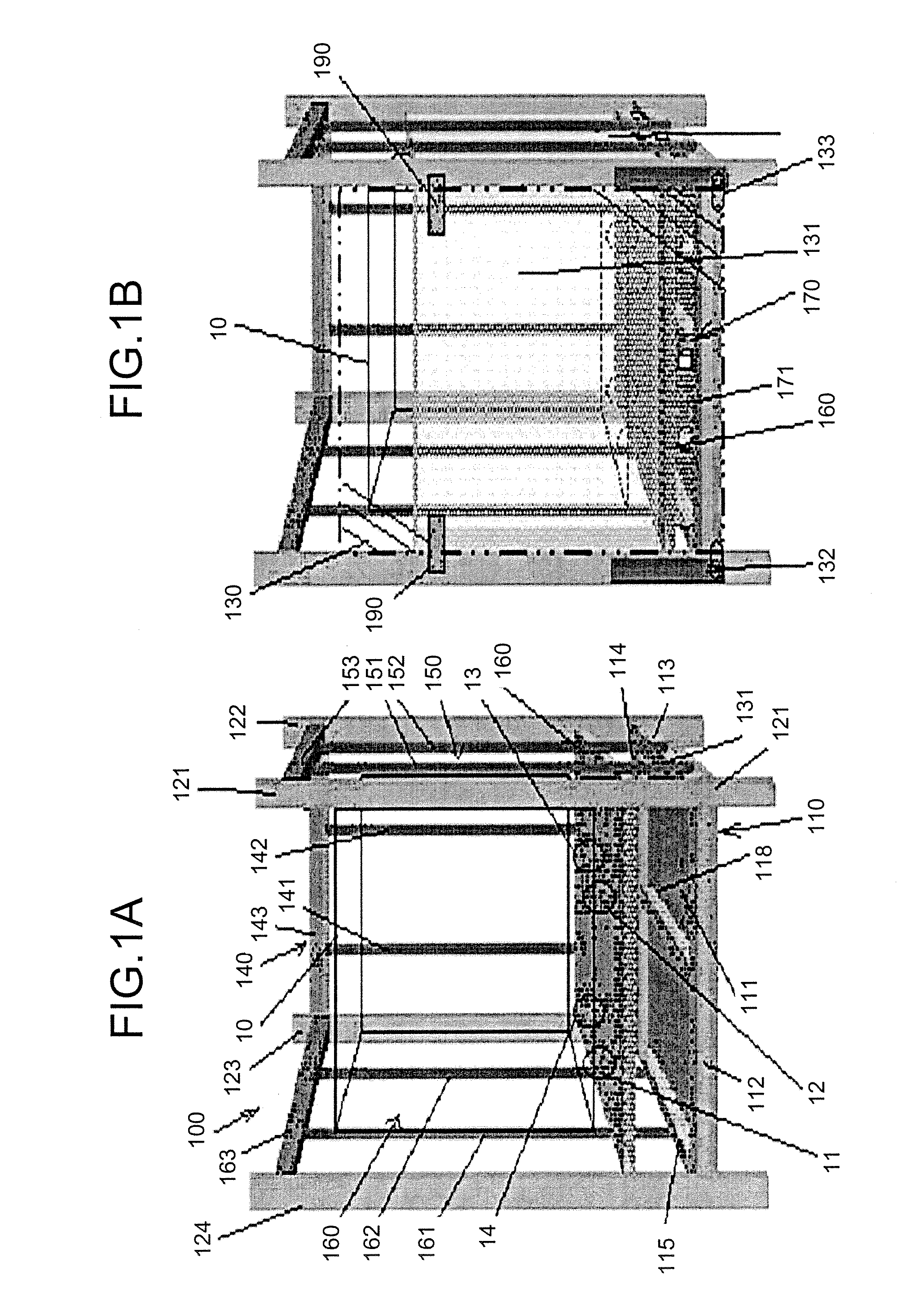
[0053] A packaging device 100 is for packaging a product 10, and as shown in FIGS. 1A and 1B, four casters 11, 12, 13, and 14 are fitted to the product 10. The packaging device 100 includes a bottom base 110, four support members 121, 122, 123, and 124 arranged upright on four corners of the bottom base 110, and also serving as legs of the bottom base 110, a front member 130 detachably fitted to the bottom base 110 and forming a front wall, a rear member 140 fitted to the bottom base 110 and forming a rear wall, a side member 150 fitted to the bottom base 110 and forming a right wall, a side member 160 forming a left wall, a buffer member 170 arranged on the bottom base 110 and formed of PET-bottles 171, which are multiple sealed containers containing a gas sealed therein, and a mounting base 180 arranged on the buffer member 170, on which an article is mounted.

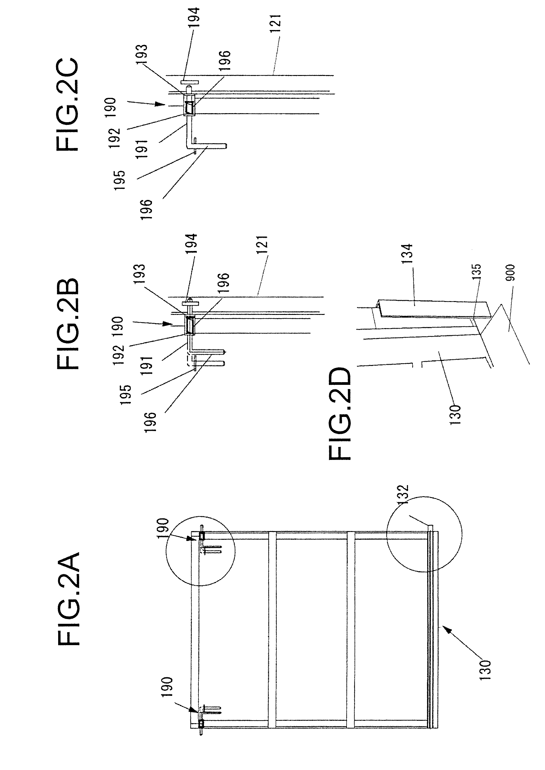
[0054] The packaging device 100 according to this embodiment includes locking devices 190, which fix the front member 130 ...

second embodiment

[0096] In the bottom base 210, as shown in FIGS. 17, 18, and 19, frames 212, 213, 214, and 215 are arranged on four sides of a rectangular plate member 211, and reinforcing members 217 and 218 are arranged on the underside of the plate member 211 in a pattern in the shape of a well crib. legs 261, 262, and 263 are arranged below the bottom base 210, to form a fork inserting portion of the forklift. Reference numeral 236 in FIG. 19 denotes a reinforcing corner plate.

[0097] According to the second embodiment, pillar members include lower pillar members 231, 232, 233, and 234 arranged on the bottom base 210, and two pairs of, in total four, upper pillar members 241 and 242 (since two upper pillar members constituting the right side member are not shown in FIG. 19, reference numerals thereof are omitted) constituting the upper side members 240 to be detachably provided thereon.

[0098] Left and right side members are respectively formed of the lower side member 230 provided between the ...

third embodiment

[0108] as shown in FIG. 24, the buffer 300 arranged between two side members of the packaging device and the article is used as the buffer. As the buffer 300, a plurality of PET-bottles 330, which are airtight containers, with a gas being sealed in a hollow box member 310, are arranged along the apparatus with the caps being arranged upward. According to this configuration, the bodies of the PET-bottles in the buffer 300 can absorb the impacts from the side of the packaging device, with respect to lateral vibrations.

[0109] According to an embodiment of the present invention, not only the impact against the article, which occurs during transportation, can be alleviated by the buffer, but also the packaging device can be used repeatedly. Accordingly, the investment for plant and equipment, the cost, and the time of packaging can be reduced, and parts control can be facilitated. Furthermore, the PET-bottles are not disposed of as a waste and can be reused, fixation and releasing of th...


PUM


Abstract

A packaging device includes a bottom base with legs; a front member detachable to the bottom base to form a front wall; a rear member to form a rear wall; two side members to form left and right side walls; a buffer member arranged on the bottom base and formed of a plurality of airtight containers in which gas is filled; and a mounting base on which an article is mounted. The front member is formed turnably with a bottom end thereof being put adjacent to the bottom base, to be used as a tilted table for loading and unloading the article, including an angle regulating member that restricts a tilt angle of the front member with respect to the bottom base.

Description

CROSS-REFERENCE TO RELATED APPLICATIONS [0001] The present document incorporates by reference the entire contents of Japanese priority document, 2005-195078 filed in Japan on Jul. 4, 2005 and 2006-090024 filed in Japan on Mar. 29, 2006. BACKGROUND OF THE INVENTION [0002] 1. Field of the Invention [0003] The present invention relates to a packaging device and a buffer, and more particularly, to a packaging device in which an article is mounted on a bottom base, side members are arranged in front and back and left and right of the bottom base, and a ceiling member is arranged at the top, and a buffer used together with the packaging device. [0004] 2. Description of the Related Art [0005] It is one of major concerns of product manufacturers to transport articles that should be handled carefully at the time of transportation, for example, a manufactured product like an image forming apparatus, such as a copying machine, a printer, and a facsimile machine, from a production plant to an i...

Claims


Application Information

Patent Timeline
Patent Type & Authority Applications(United States)
IPC IPC(8): B65D88/00
CPCB65D19/12B65D2519/00975B65D88/542B65D2519/00024B65D2519/00059B65D2519/00129B65D2519/00164B65D2519/00233B65D2519/00273B65D2519/00293B65D2519/00318B65D2519/00338B65D2519/00497B65D2519/00512B65D2519/00656B65D2519/00666B65D2519/00805B65D2519/00815B65D81/052Y02W30/80
Inventor NARUISHI, MOKUGODA, HIDEYUKIABE, TSUYOSHIISHIHARA, SATOSHIISHIKAWA, SAKAE
Owner RICOH KK
Why Eureka
Try Eureka