Display apparatus, and driving circuit for the same

a technology of display apparatus and driving circuit, which is applied in the direction of instruments, static indicating devices, electroluminescent light sources, etc., can solve the problems of large power consumption in the interface between the control circuit b and the response speed, and achieve the effect of reducing the deviation of the current valu

Active Publication Date: 2007-01-04
RENESAS ELECTRONICS CORP
View PDF8 Cites 238 Cited by
  • Summary
  • Abstract
  • Description
  • Claims
  • Application Information

AI Technical Summary

Benefits of technology

[0026] Therefore, an object of the present invention is to provide a drive circuit with monotonous increase and a reduced current value deviation.
[0027] Also, another object of the present invention is to provide a drive circuit whose circuit scale can be reduced.

Problems solved by technology

However, the method has a problem in a response speed.
Therefore, it is not suitable for a large-size display such as a television screen.
In addition, power consumption becomes large in an interface between the control circuit 103 and the data line driving circuit 101 because the number of bits is increased.
As a result, it is difficult to drive the data line in a low current level.
Therefore, if the data line driving circuit is formed on the glass substrate, ununiform display tends to be generated easily.
Forming the data line driving circuit 101 on the silicon substrate, it is difficult that the quasi-addition circuit 153 included in the data line driving circuit 101 has the same characteristic as the pixel 105 formed on the glass substrate, resulting in decrease in the reliability of the circuit.
Furthermore, when a switching is carried out from the voltage drive to the current drive, glitch is generated sometimes in the conventional display apparatus 100.
The glitch causes lowering image quality, especially in a low brightness (low current region) because a voltage is drifted from a desired voltage, even if the voltage is precharged to a desired voltage at high speed by the voltage driver.
However, in the current copy-type current drive method, since the magnitude of current supplied from a constant current circuit is especially small on the side of low brightness, a data line 205 and a pixel 206 cannot be driven within a predetermined drive period.
However, there are some problems in the conventional constant current circuit.
Therefore, there is possibility of loss of monotonous increase due to a deviation of the constant current sources in current value.
Also, since the plurality of constant current sources are provided to drive one data line, a circuit region of the constant current sources becomes large in circuit scale and has a large parasite capacitance to elongate the current drive period.

Method used


Image

  • Display apparatus, and driving circuit for the same
  • Display apparatus, and driving circuit for the same
  • Display apparatus, and driving circuit for the same

Examples


first embodiment

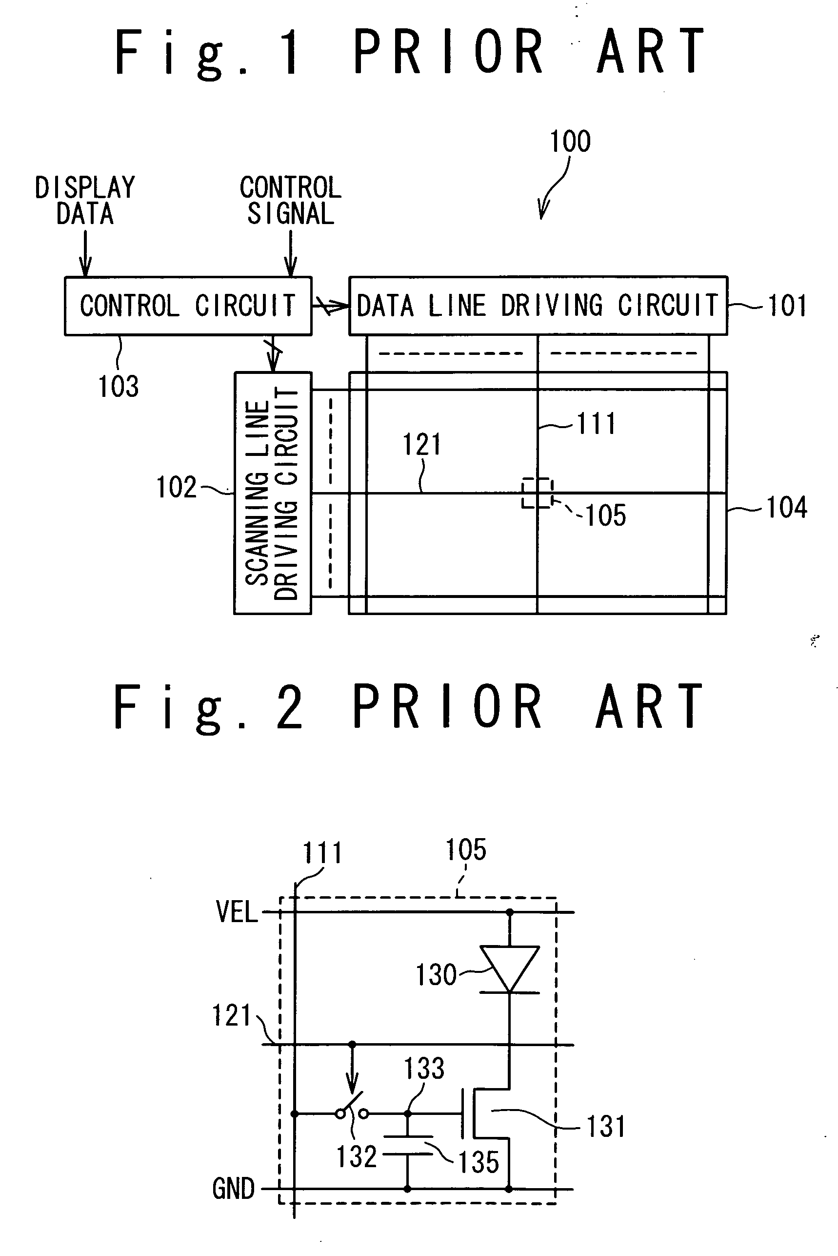
[0102]FIG. 5 is a block diagram showing the circuit configuration of a display panel apparatus according to the first embodiment of the present invention. As shown in FIG. 5, the display apparatus 10 includes a data line driving circuit 1, a scanning line driving circuit 2, a control circuit 3, and a display panel 4. The display panel 4 has a plurality of data lines 6 arranged in a column direction. Each data line 6 is connected with the data line driving circuit 1. Similarly, the display panel 4 has a plurality of scanning lines 7 arranged in a row direction. Each scanning line 7 is connected with the scanning line driving circuit 2. In addition, the display panel 4 has a pixel 5 at each of the intersections of the plurality of data lines 6 and the plurality of scanning lines 7.

[0103] The display apparatus 10 shown in FIG. 5 is driven by the sequential line driving method. The scanning line driving circuit 2 drives the plurality of scanning lines 7 in a predetermined order in resp...

second embodiment

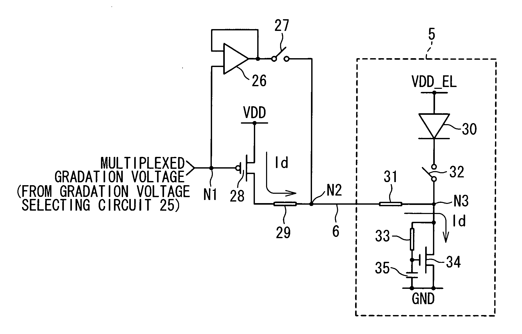
[0148] The second embodiment of the present invention will be described below. FIG. 23 is a block diagram showing the configuration of a D / A conversion circuit 14a in the second embodiment of the present invention. As shown in FIG. 23, the D / A conversion circuit 14a in the second embodiment includes a first switch 61, a second switch 62, and a capacitor 63 in addition to the configuration of the above-mentioned D / A conversion circuit 14. The first switch 61 is connected between the node N1 and the input of the voltage driver 26. The capacitor 63 is connected between the input of the voltage driver 26 and the ground potential. The voltage driver 26, the first switch 61 and the capacitor 63 configure a sample-hold circuit. Also, the second switch 62 is connected between the node 1 and the current driver 28.

[0149] An operation of the D / A conversion circuit 14a shown in FIG. 23 will be described below. The D / A conversion circuit 14a turns the first switch 61 off immediately before the ...

third embodiment

[0151] The third embodiment of the present invention will be described below. FIG. 24 is a block diagram showing the configuration of a gradation voltage generating circuit 15a in the data line driving circuit 1 according to the third embodiment of the present invention. As shown in FIG. 24, the gradation voltage generating circuit 15a in the third embodiment includes a first gradation setting register 71, a second gradation setting register 72, a multiplexer 73, and a gradation voltage generator 74. The first gradation setting register 71 is a memory circuit to store the first gradation setting data for the plurality of first gradation voltages. Similarly, and the second gradation setting register 72 is a memory circuit to store the second gradation setting data for the plurality of second gradation voltages. The multiplexer 73 selects one of the gradation setting data stored in the first gradation setting register 71 and the second gradation setting register 72, and outputs the se...


PUM


Abstract

A drive circuit which outputs an output signal to an output terminal, includes a drive transistor configured to output a gradation current to the output terminal; a single differential amplifier; a resistance element connected with the drive transistor; and a plurality of switches. The plurality of switches are controlled such that a precharge voltage is outputted from the differential amplifier to the output terminal in a first period while blocking off an output from the drive transistor and such that a gradation current is outputted from the drive transistor to the output terminal in a second period after the first period.

Description

CROSS REFERENCE [0001] This patent application is a continuation-in-part application of the U.S. patent application Ser. No. 11 / 045,608.BACKGROUND OF THE INVENTION [0002] 1. Field of the Invention [0003] The present invention relates to a display apparatus such as a flat-panel display apparatus, a driving circuit for the display apparatus, and a semiconductor device for the driving circuit. [0004] 2. Description of the Related Art [0005] The importance of an apparatus to mediate a man or woman and a machine (man-machine interface) has been increased with the advance of computer technology. Especially, a display apparatus as one of the man-machine interfaces on the output side is required to have higher performance. The display apparatus displays data outputted from a computer for a man to visibly recognize the data. Various kinds of display apparatuses are commercially available. A typical display apparatus is a flat-panel display and is widespread. [0006] The flat-panel display app...

Claims


Application Information

Patent Timeline
Patent Type & Authority Applications(United States)
IPC IPC(8): G09G3/30G09G3/20H01L51/50G09G3/32H05B33/14
CPCG09G3/3233G09G3/3283G09G3/3291G09G2320/0276G09G2310/0251G09G2310/027G09G2300/0842G09G3/30G09G3/20
Inventor HASHIMOTO, YOSHIHARUYONEYAMA, TERU
Owner RENESAS ELECTRONICS CORP
Why Eureka
Try Eureka