
Fresnel lens sheet, transmission screen and rear projection display

a technology of transmission screen and lens sheet, which is applied in the direction of optics, projectors, instruments, etc., can solve the problems of affecting the efficiency of fresnel lens sheet production, and the problem that the image displayed on the rear projection screen is distorted will be more significant, so as to achieve the effect of reducing the thickness of the display, facilitating the release of fresnel lens sheet, and improving the efficiency of the production o

Active Publication Date: 2007-01-04
DAI NIPPON PRINTING CO LTD
View PDF3 Cites 9 Cited by
  • Summary
  • Abstract
  • Description
  • Claims
  • Application Information

AI Technical Summary

Benefits of technology

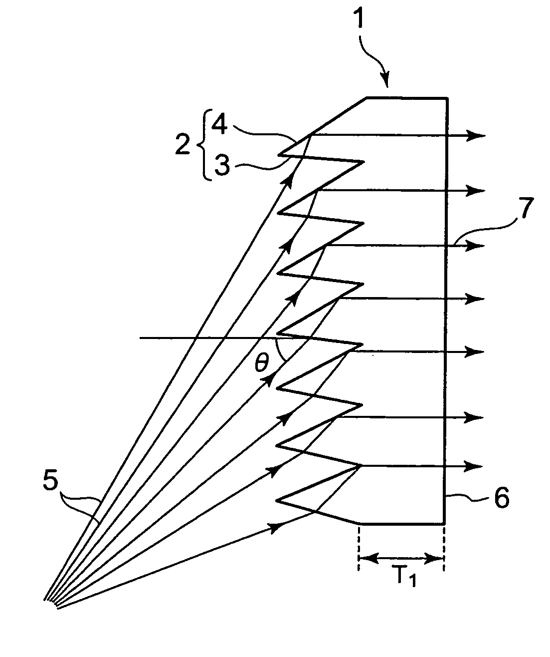
[0009] Further, the above-described Fresnel lens sheet having a total reflection Fresnel lens is produced by the steps of: filling a Fresnel-lens-sheet-forming flat mold with a molding resin; curing the molding resin in the mold; and then releasing the Fresnel lens sheet from the mold. The problem with the production of the Fresnel lens sheet having a total reflection Fresnel lens, in particular, has been that: since the Fresnel lens element of the Fresnel lens sheet 1 as is, for example, shown in FIG. 12B (in which unit total reflection Fresnel lenses 2, each unit lens composed of a light-entering surface 3 and a total reflection surface 4, are inclined at a predetermined angle in the direction of incidence of the imaging light 5) and the mold (not shown in the figure) are meshing with each other, it is very difficult to release the Fresnel lens sheet from the mold because the Fresnel lens sheet is less flexible when it is thick. For this reason, in addition to the above-described demand for a Fresnel lens sheet that scarcely makes the projected image distorted, there is a strong demand for a Fresnel lens sheet that can improve the efficiency of mold releasing operation that is conducted in the production of the Fresnel lens sheet.
[0028] Furthermore, according to the rear-projection-type display of the present invention, since the display comprises the Fresnel lens sheet of the present invention that scarcely makes the projected image distorted, it becomes possible to make the display significantly thinner.

Problems solved by technology

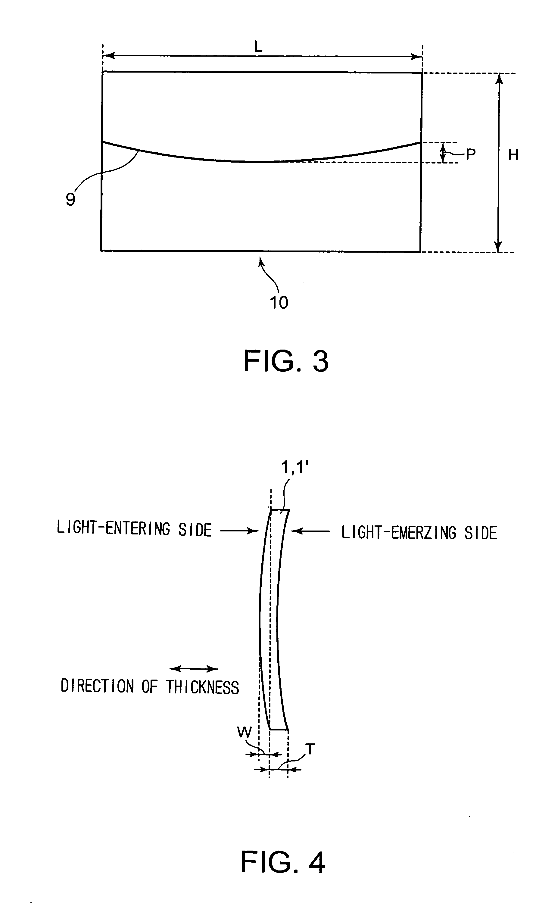
Further, for example, when the Fresnel lens sheet undergoes deflection, although a portion of the Fresnel lens that is in the center of the Fresnel lens sheet gets out of position in the direction of the thickness of the sheet, a portion of the Fresnel lens that is in the periphery of the Fresnel lens sheet does not get out of position so much, so that the image displayed on the rear projection screen undergoes distortion.
It is, therefore, anticipated that the problem that the image displayed on the rear projection screen gets distorted will be more significant.
However, the fact is that no consideration has so far been given to this problem at all.
The problem with the production of the Fresnel lens sheet having a total reflection Fresnel lens, in particular, has been that: since the Fresnel lens element of the Fresnel lens sheet 1 as is, for example, shown in FIG. 12B (in which unit total reflection Fresnel lenses 2, each unit lens composed of a light-entering surface 3 and a total reflection surface 4, are inclined at a predetermined angle in the direction of incidence of the imaging light 5) and the mold (not shown in the figure) are meshing with each other, it is very difficult to release the Fresnel lens sheet from the mold because the Fresnel lens sheet is less flexible when it is thick.

Method used


Image

  • Fresnel lens sheet, transmission screen and rear projection display
  • Fresnel lens sheet, transmission screen and rear projection display
  • Fresnel lens sheet, transmission screen and rear projection display

Examples


first embodiment

(First Embodiment)

[0067] First of all, a Fresnel lens sheet according to the first embodiment of the present invention will be described.

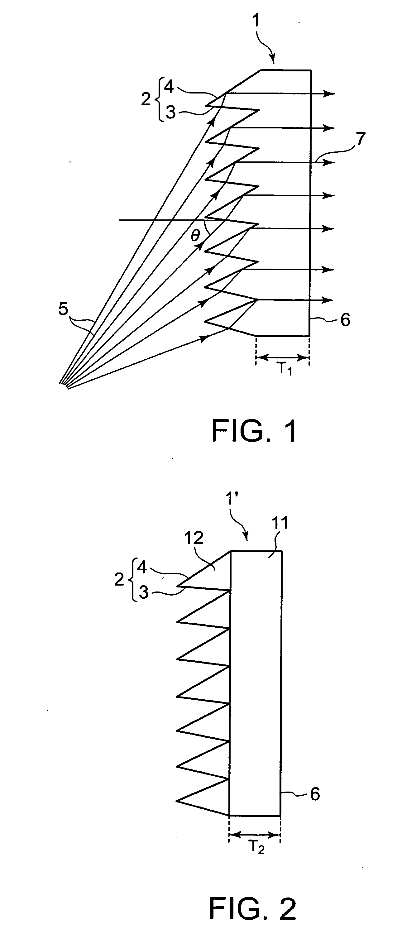
[0068] As shown in FIG. 1, a Fresnel lens sheet 1 according to the first embodiment of the present invention has a single layer structure and is composed of a total reflection Fresnel lens 2. Namely, the Fresnel lens sheet 1 is single-layer one having a plurality of integrally formed unit total reflection Fresnel lenses 2 arranged on the light-entering side, each unit lens having a light-entering surface 3 and a total reflection surface 4 that totally reflects a part of or all of the imaging light 5 that has passed through the light-entering surface 3 to deflect the light in the desired direction, and fulfills the above-described relationship.

[0069] A transparent resin selected from styrene resins, acryl-styrene copolymer resins, polycarbonate resins, etc. is preferably used to form the Fresnel lens sheet 1. The Fresnel lens sheet 1 is produced b...

second embodiment

(Second Embodiment)

[0080] Next, a Fresnel lens sheet according to the second embodiment of the present invention will be described.

[0081] As shown in FIG. 2, a Fresnel lens sheet 1′ according to the second embodiment of the present invention is of combined type and is composed of a base 11 and a Fresnel lens element 12 formed on the base 11. Namely, like in the above-described first embodiment, the Fresnel lens sheet 1′ has a plurality of unit total reflection Fresnel lenses 2 arranged on the light-entering side, each unit lens having a light-entering surface 3 and a total reflection surface 4 that totally reflects a part of or all of the imaging light 5 that has passed through the light-entering surface 3 to deflect the light in the desired direction, and fulfills the above-described relationship.

[0082] A transparent resin selected from styrene resins, acryl-styrene copolymer resins, polycarbonate resins, and the like is preferably used to form the base 11 of the Fresnel lens she...

third embodiment

(Third Embodiment)

[0087] Next, a Fresnel lens sheet according to the third embodiment of the present invention will be described.

[0088] As shown in FIG. 13A, a Fresnel lens sheet 41 according to the third embodiment of the present invention is of combined type and is composed of a Fresnel-lens-molded sheet 13 and a backing sheet 14 that is laminated to the light-emerging surface of the Fresnel-lens-molded sheet 13. Namely, like in the above-described first embodiment, the Fresnel lens sheet 41 has a plurality of unit total reflection Fresnel lenses 2 arranged on the light-entering side, each unit lens having a light-entering surface 3 and a total reflection surface 4 that totally reflects a part of or all of the imaging light 5 that has passed through the light-entering surface 3 to deflect the light in the desired direction, and, as a whole, fulfills the above-described relationship. The Fresnel lens sheet 41 is characterized in that the Fresnel-lens-molded sheet 13 is single-laye...


PUM


Abstract

The present invention provides a Fresnel lens sheet that scarcely makes the projected image distorted, and others. The Fresnel lens sheet has a plurality of unit total reflection Fresnel lenses arranged on the light-entering side, each unit lens having a light-entering surface and a total reflection surface that totally reflects a part of or all of the imaging light that has passed through the light-entering surface to deflect the light in the desired direction. This Fresnel lens sheet is formed so that it fulfills the relationship H1×H1 / (10×E1×T1×T1)≦3L / 2000, where H1 represents the length (cm) in the vertical direction of the Fresnel lens sheet; L1, the length (cm) in the horizontal direction of the Fresnel lens sheet; T1, the thickness (cm) of the Fresnel lens sheet; and E1, the modulus of elasticity (kgf / cm2) of the Fresnel lens sheet. Further, by using, to make up the Fresnel lens sheet, a Fresnel-lens-molded sheet having unit total reflection Fresnel lenses and a backing sheet laminated to the light-emerging surface of the Fresnel-lens-molded sheet, improvement in the efficiency of mold releasing operation that is conducted in the production of the Fresnel lens sheet is achieved.

Description

BACKGROUND OF THE INVENTION [0001] 1. Field of the Invention [0002] The present invention relates to a Fresnel lens sheet that scarcely makes the projected image distorted, to a rear projection screen, and to a rear-projection-type display. [0003] 2. Background Art [0004] A projection television, or a rear-projection-type display, comprises a rear projection screen on which imaging light from a light source that has been spread is projected. This rear projection screen is usually composed of: a Fresnel lens element for refracting the imaging light from the light source that has been spread and projected on the Fresnel lens element, to make the light parallel or almost parallel and emitting this light toward the viewer side; and a lenticular lens element for scattering the parallel or almost parallel light emerging from the Fresnel lens element to provide an image to viewers who are in a wide area. Although a CRT light source of three-tube type by which light of three primary colors ...

Claims


Application Information

Patent Timeline
Patent Type & Authority Applications(United States)
IPC IPC(8): G03B21/60G03B21/56G02B3/08G03B21/10G03B21/62G03B21/625
CPCG03B21/625G02B3/08G03B21/62G03B21/60G03B21/56
Inventor SEKIGUCHI, HIROSHI
Owner DAI NIPPON PRINTING CO LTD
Learn More