
Drive connection mechanism, and image forming apparatus having the drive connection mechanism

a technology of drive connection and drive shaft, which is applied in the direction of electrographic process apparatus, instruments, optics, etc., can solve the problems of insufficient centering of photoconductive drum and drive shaft, and insufficient formation of satisfactory images, etc., and achieve the effect of accurate centering of drive unit and driven uni

Inactive Publication Date: 2007-01-04
KK TOSHIBA +1
View PDF3 Cites 42 Cited by
  • Summary
  • Abstract
  • Description
  • Claims
  • Application Information

AI Technical Summary

Benefits of technology

[0011] It is an object of the invention to provide a drive connection mechanism which is configured to connect a drive unit to a driven unit without generating a backlash, enable accurate centering of the drive unit and driven unit, and transmit the rotation of the drive unit stably to the driven unit, and an image forming apparatus having the drive connection mechanism.

Problems solved by technology

However, in the above-mentioned drive connection mechanism, as the coupling gear is provided slidably along the drive shaft, the coupling gear can be securely engaged with the internal gears of the photoconductive drum, but a clearance exists between the coupling gear and causes a backlash.
Namely, the clearance causes a backlash when the driving force is transmitted from the drive shaft to the photoconductive drum.
By using the above conventional drive connection mechanism, a backlash can be decreased and a driving force can be transmitted from the drive shaft to a photoconductive drum, but the centering of the photoconductive drum and drive shaft is insufficient, the photoconductive drum swings a little during rotation, and a satisfactory image is not formed.

Method used


Image

  • Drive connection mechanism, and image forming apparatus having the drive connection mechanism
  • Drive connection mechanism, and image forming apparatus having the drive connection mechanism
  • Drive connection mechanism, and image forming apparatus having the drive connection mechanism

Examples


Embodiment Construction

[0035] Embodiments of the present invention will be explained in detail hereinafter with reference to the accompanying drawings.

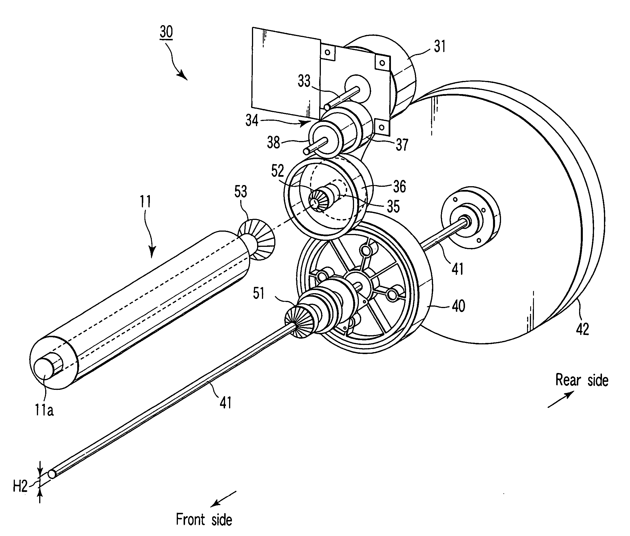
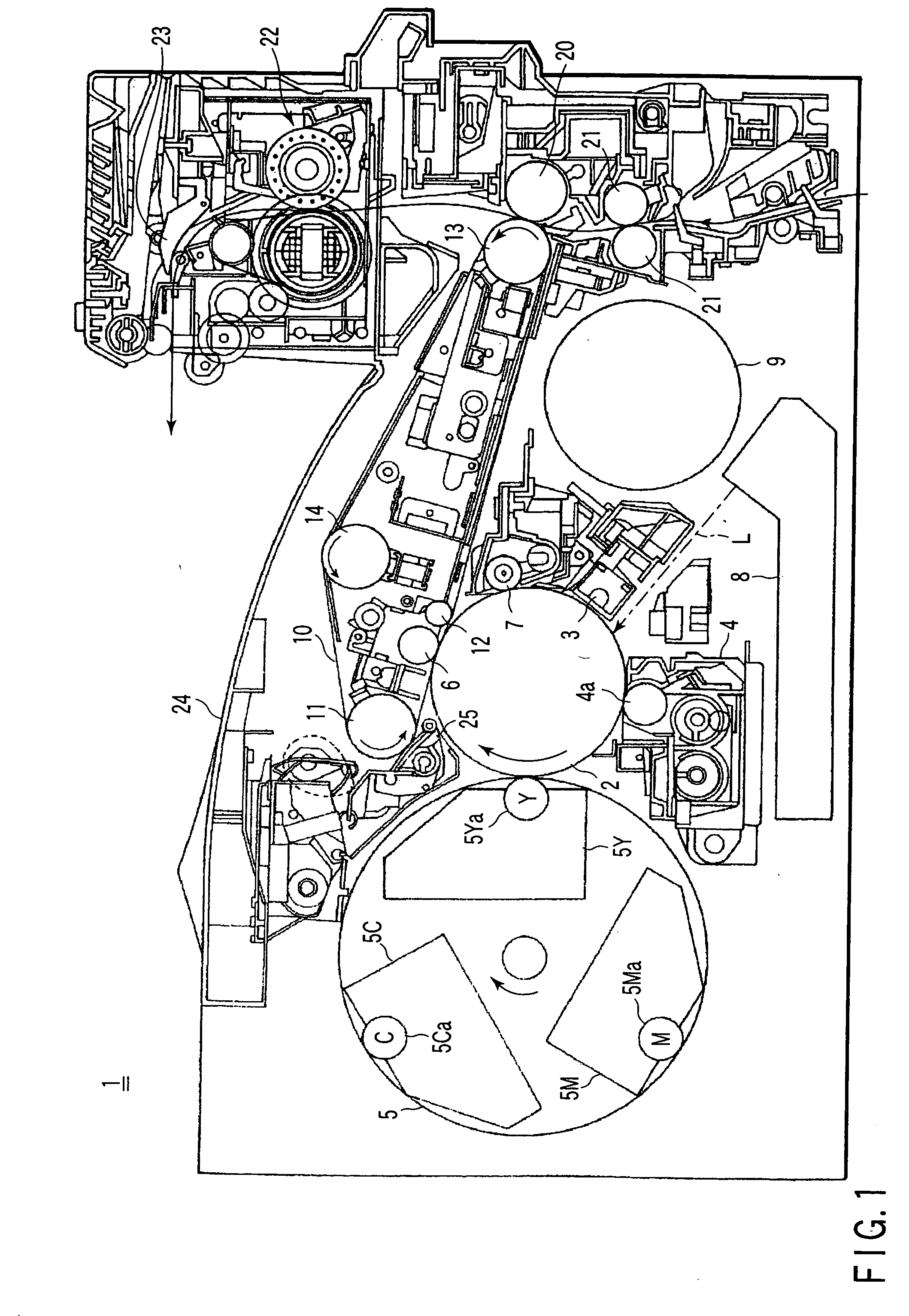
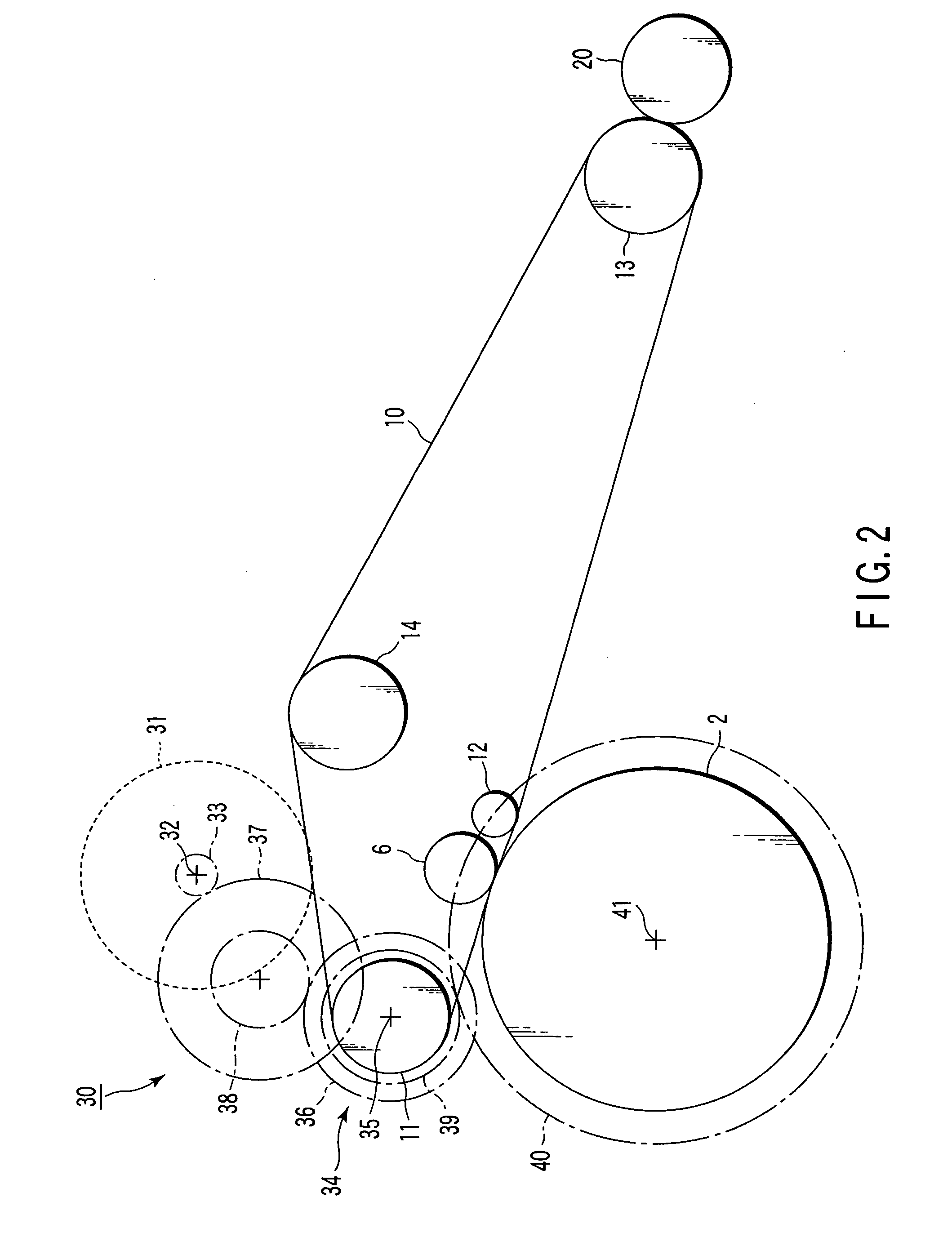
[0036]FIG. 1 is a schematic diagram of an internal structure of MFP (Multi-Functional Printer) 1 of an intermediate transfer system as an image forming apparatus according to an embodiment of the invention. FIG. 2 is a diagrammatic sketch showing a drive transmission system of a rotary drive unit described later incorporated in the MFP 1 of FIG. 1. FIG. 3 is a schematic perspective view showing the rotary drive unit of FIG. 2. In the description, the invention is applied to the MFP 1, but the invention may be applied to other image forming apparatus, such as an electrophotographic digital copier.

[0037] As shown in FIG. 1, in the main body of MFP 1, a photoconductive drum 2 as an image holding unit is provided rotatably in the clockwise direction. Around the photoconductive drum 2, a charging unit 3, a black color developing unit 4, a rotary color developi...


PUM


Abstract

A drive connection mechanism has a sliding unit which is fixed to a drive shaft extending through the photoconductive drum, a convex coupling gear which has three coupling members fixed slidably to splines formed in the periphery of the sliding unit, a compressing spring which energizes the coupling gar, and a concave coupling gear which is provided in the drum to receive and fit the convex coupling gear. When the convex coupling gear is pressed to the concave coupling gear, a force from the tapered surface to the inside acts on each coupling member. Then, the bevel gear of the convex coupling gear is stuck to the bevel gear of the concave coupling gear, the internal gears of the convex coupling gear is stuck to the splines of the drive shaft, and the centers of the drive shaft and photoconductive drum are aligned.

Description

CROSS-REFERENCE TO RELATED APPLICATIONS [0001] This application is based upon and claims the benefit of priority from prior Japanese Patent Application No. 2005-193151, filed Jun. 30, 2005, the entire contents of which are incorporated herein by reference. BACKGROUND OF THE INVENTION [0002] 1. Field of the Invention [0003] The present invention relates to a drive connection mechanism to connect a drive unit and a driven unit. In particular, the present invention relates to a drive connection mechanism to connect a photoconductive drum of a copier or printer and its drive shaft, and an image forming apparatus having the drive connection mechanism. [0004] 2. Description of the Related Art [0005] In a known drive connection mechanism to connect a photoconductive drum of a copier to a drive shaft provided in a main body of a copier, a coupling gear is provided rotatably together with a drive shaft and slidably along the axial direction of the drive shaft. In the periphery of the couplin...

Claims


Application Information

Patent Timeline
IPC IPC(8): G03G15/00
CPCG03G15/757G03G2221/1657G03G2221/1654
Inventor HARA, KAZUHIROSHISHIKURA, KENICHIRO
Owner KK TOSHIBA
Features
  • Generate Ideas
  • Intellectual Property
  • Life Sciences
  • Materials
  • Tech Scout
  • Unparalleled Data Quality
  • Higher Quality Content
  • 60% Fewer Hallucinations
Learn More