

Organic electroluminescence device
a technology of electroluminescence device and organic material, which is applied in the direction of solid-state devices, discharge tubes/lamp details, natural mineral layered products, etc., can solve the problems of insufficient efficiency of light emission, insufficient average life of less than 150 hours, and device with insufficient purity of red light, etc., to achieve excellent color purity and high light emission efficiency
- Summary
- Abstract
- Description
- Claims
- Application Information
AI Technical Summary
Benefits of technology
Problems solved by technology
Method used
Image

Examples
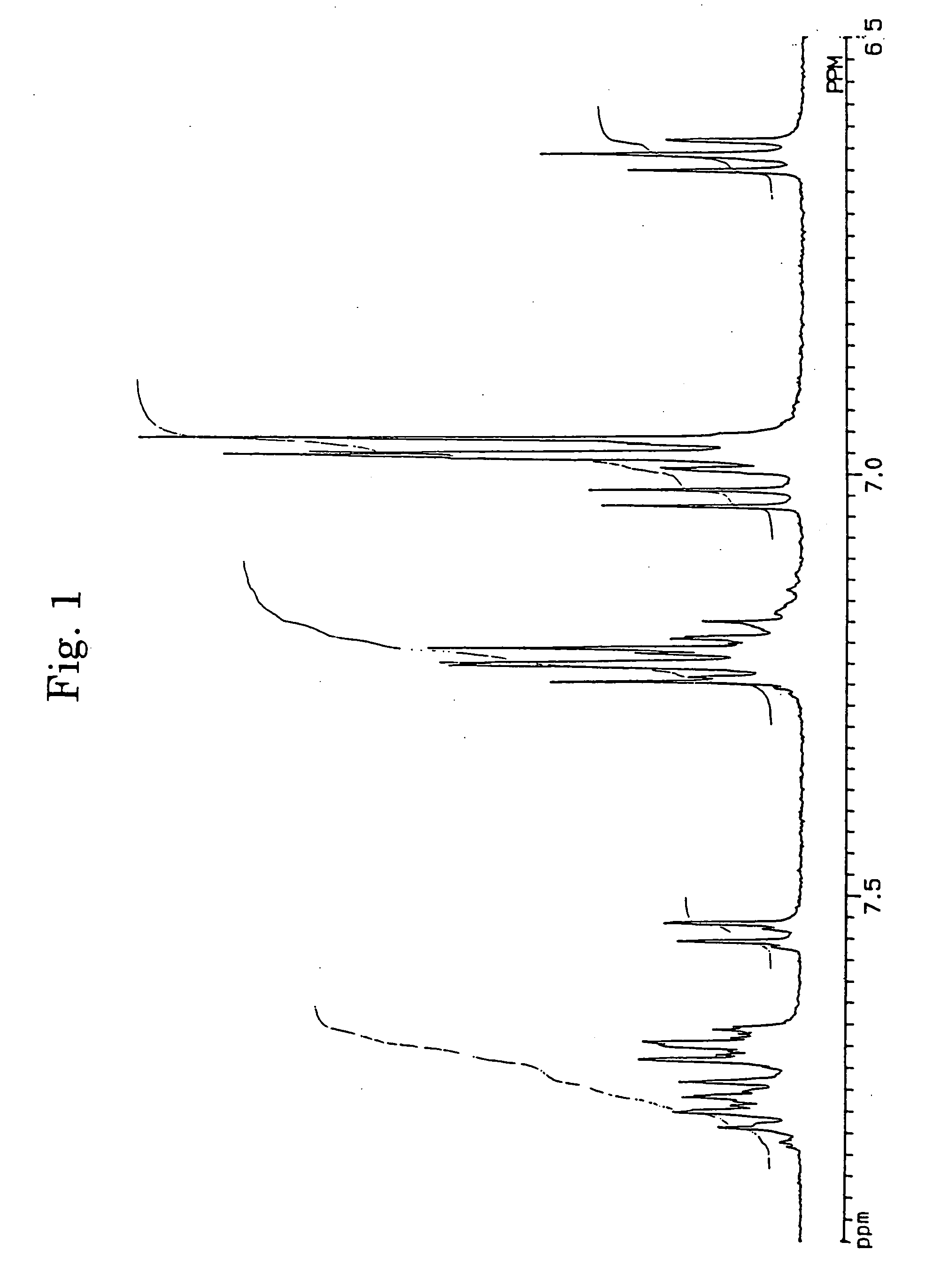
synthesis example 1
Compound A-1
[0060] 3,10- and 3,11-Bisdiphenylamino-7,14-diphenylacenaphtho[1,2-k]fluoranthene was synthesized via the reaction route shown in the following:
[0061] (A) Synthesis of 3,10- and 3,11-dibromo-7,14-diphenylacenaphtho[1,2-k]fluoranthenes
[0062] In accordance with the J. B. Allen's process, 3,10- and 3,11-dibromo-7,14-diphenylacenaphtho[1,2-k]fluoranthenes (7) were synthesized using acenaphthenequinone (1) as the starting material via 7,14-diphenylacenaphtho[1,2-k]fluoranthene (6). The structures of 3,10- and 3,11-dibromo-7,14-diphenylacenaphtho[1,2-k]fluoranthenes were identified from FD-MS (the field desorption mass spectra) and the 1H-NMR spectra. The chemical shifts in 1H-NMR agreed with the measured values reported by Allen (J. D. Debad, A. I. Bard, J. Chem. Soc., Vol. 120, 2476 (1998)).
[0063] (B) Synthesis of 3,10- and 3,11-diphenylamino-7,14-diphenylacenaphthofluoranthenes (Compound A-1)
[0064] Into 150 ml of toluene, 3.56 g (5.6 mmole) of 3,10- and 3,11-dibromo-7...
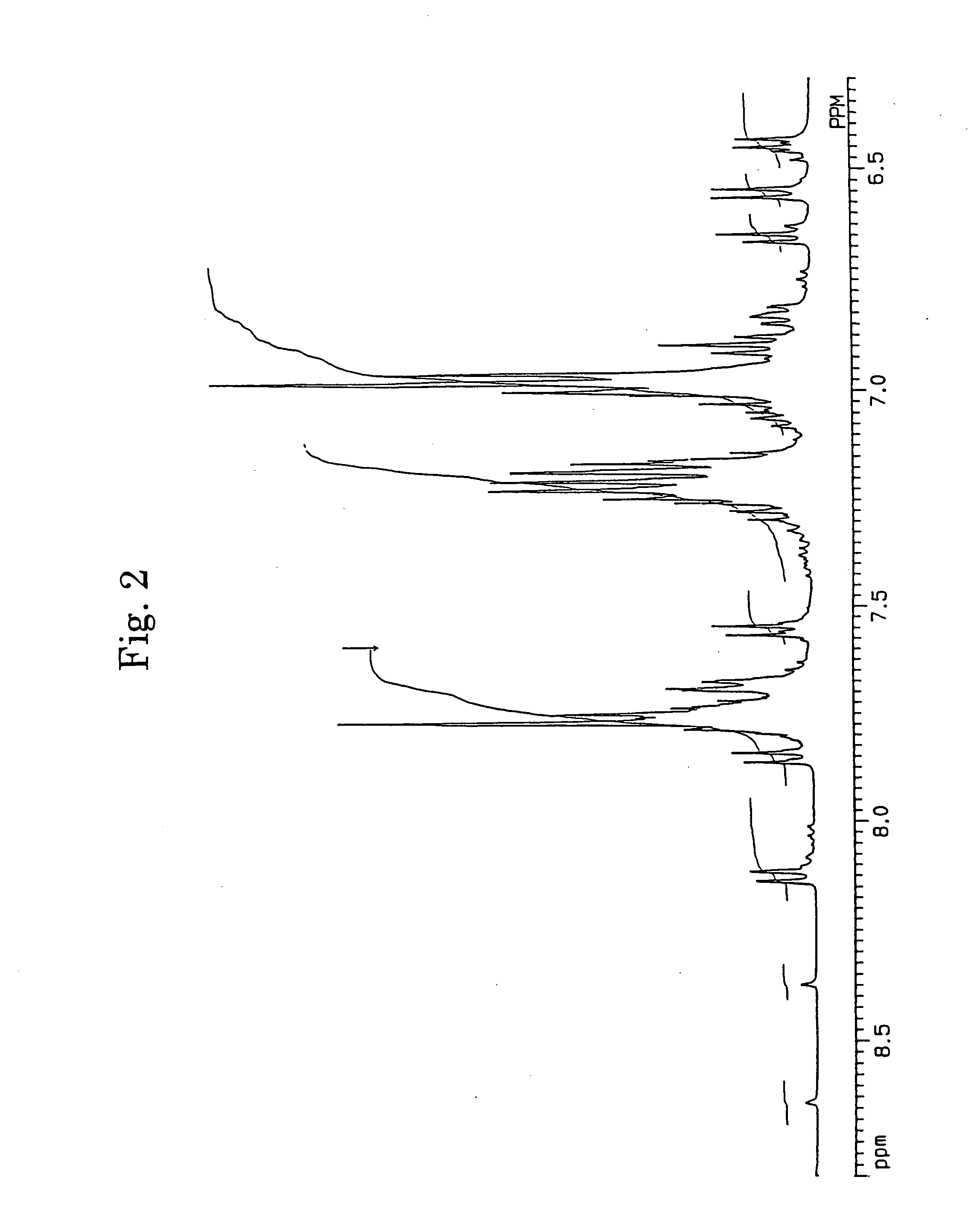
synthesis example 2
Compound A-16
[0066] The reaction was conducted in accordance with the same procedures as those conducted in Synthesis Example 1 (B) except that 2.31 g (11.7 mmole) of p,p′-ditolylamine was used in place of diphenylamine. After the reaction was completed, the reaction mixture was filtered. The filtrate was washed with water and concentrated and a red powdery solid was obtained. The obtained solid was fractionated in accordance with the column chromatography using a column packed with silica gel and 2.9 g of the main component having a high purity was obtained. The main component was confirmed to be Compound A-16 from FD-MS (868).
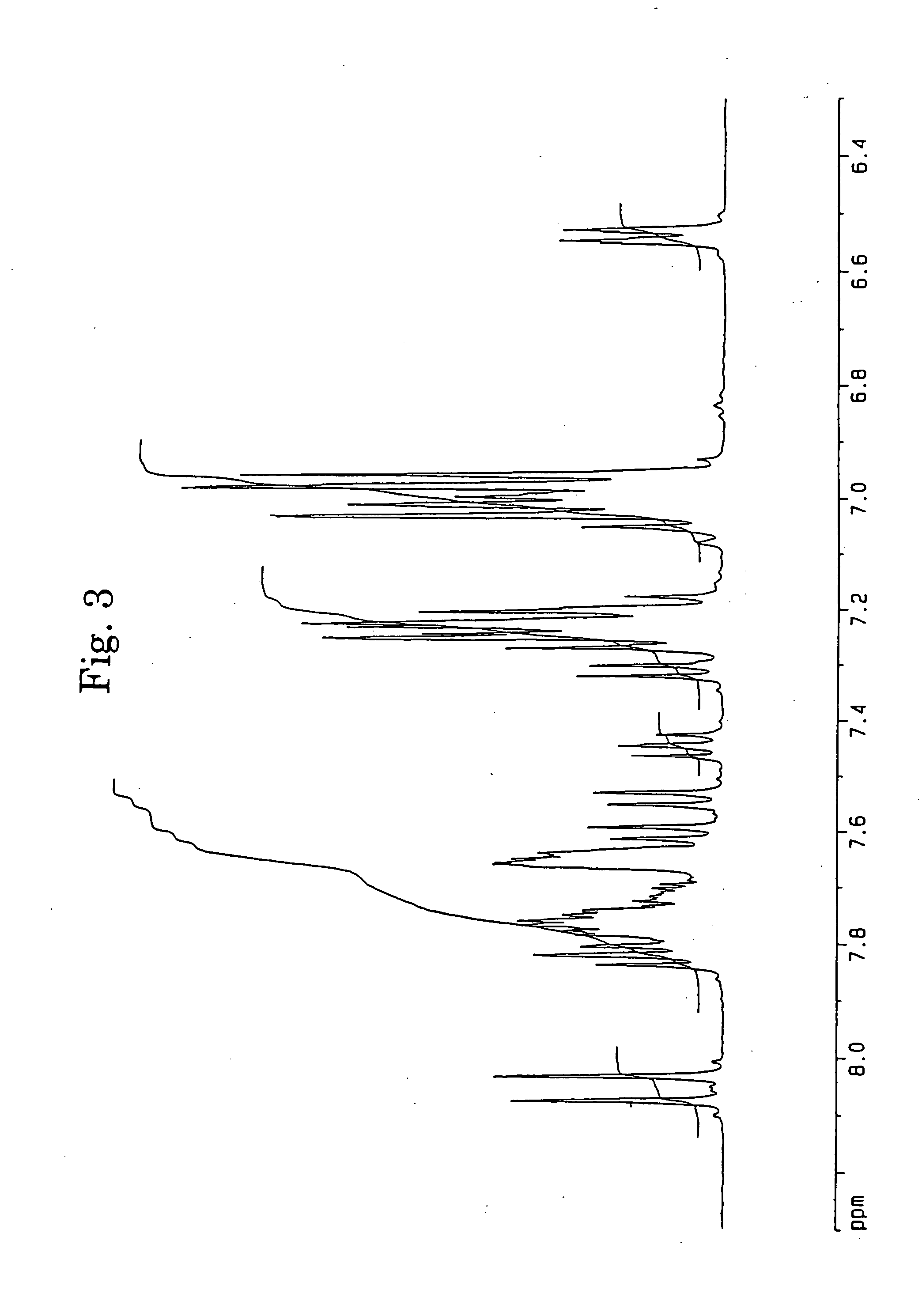
synthesis example 3
Compound B-15
[0067] The reaction was conducted in accordance with the same procedures as those conducted in Synthesis Example 1 (B) except that 2.27 g (11.7 mmole) of iminostilbene was used in place of diphenylamine. After the reaction was completed, the product precipitated in the reaction mixture was separated, repeatedly washed with acetone and water and dried and 3.4 g of a red orange powdery solid was obtained. The obtained solid was dissolved in tetrahydrofuran and fractionated in accordance with the thin layer chromatography using a thin layer of silica gel and 2.3 g of the main component having a high purity was obtained. The main component was confirmed to be Compound B-15 from FD-MS (862).
PUM
| Property | Measurement | Unit |
|---|---|---|
| glass transition temperature | aaaaa | aaaaa |
| work function | aaaaa | aaaaa |
| transmittance | aaaaa | aaaaa |
Abstract
Description
Claims
Application Information