Absorbent Article

a technology of absorbent articles and absorbent materials, applied in the field of absorbent articles, can solve the problems of difficult to prevent body fluids from leaking along the bottom cleft, difficult fold in the bottom cleft, etc., and achieve the effect of reliably folding, improving the preventive effect against leakage, and improving the fitness of the bottom covering region

Inactive Publication Date: 2007-01-04
UNI CHARM CORP
View PDF5 Cites 14 Cited by
  • Summary
  • Abstract
  • Description
  • Claims
  • Application Information

AI Technical Summary

Benefits of technology

[0011] A zone extending between the pair of lateral groove segments in front of the bottom covering region may be configured to be thicker than the bottom covering region and to protuberate on the side of the body-side surface to improve fitness of the bottom covering region to the wearer's bottom cleft and thereby to achieve further improvement of preventive effect against leak of body fluids.
[0012] The respective rear ends of the paired rear side groove segments may be contiguous to each other or not. With these rear ends being contiguous to each other, the paired rear side groove segments preferably converge on the longitudinal center line, in other words, the respective rear ends of these paired rear side groove segments preferably lie on the longitudinal center line. With these rear ends being not contiguous to each other, a middle point on an imaginary line segment extending between these rear ends of the rear side groove segments preferably lies on the longitudinal center line. So far as the rear ends of the paired rear side groove segments are positioned as has been defined above, it is ensured that a fold line appearing during use of the napkin under the guiding effect of the rear side groove segments reliably falls upon the longitudinal center line. Consequently, the bottom covering region can cover the wearer's bottom in laterally balanced manner. It is possible to provide a fold guide extending rearward from the rear end of the compressed groove along the longitudinal center line so that the article can be reliably folded along the longitudinal center line in the bottom covering region.
[0013] The compressed groove may further comprise a front side groove segment extending forward from the front ends of the respective lateral groove segments so as to connect these front ends to each other. The compressed groove comprising the lateral groove segments, the rear side groove segment and the front side groove segment may be advantageously formed as a whole in a closed loop. At a glance, the wearer has a sense of reassurance that any amount of body fluids discharged in the region surrounded by the compressed groove never leak. Indeed, the compressed groove formed in the closed loop practically assures leak-barrier effect as high as it looks.
[0014] A longitudinal distance from the rear end of the rear side groove segment to the rear end of the liquid-absorbent layer is preferably 50 mm or longer. In this way, the wearer's bottom is covered with the liquid-absorbent layer over an area sufficient to achieve effective prevention of body fluid leak and also to eliminate psychological anxiety on leak.
[0015] With the absorbent article according to this invention put on the wearer's body, the bottom covering region is folded along the rear side groove segment and become convex on the side of the body-side surface as the pressure due to movement of the wearer's thighs is exerted on this region. In such folded state, the bottom covering region fits into the wearer's bottom cleft. In this way, fitness of the article to the wearer's bottom is improved and leak of body fluids occurring along the bottom cleft is reliably prevented.

Problems solved by technology

However, in view of the fact that a zone extending behind the leak-barrier grooves has substantially the same thickness as the remaining zone, any effective and thoughtful consideration for the purpose of improvement in the leak-barrier effect can not be found in this article of prior art.
More specifically, even though the zone extending behind the leak-barrier grooves is folded in a transverse direction under a pressure laterally exerted on this zone as the article is put on the wearer's body, it will be difficult for the fold to fit into bottom cleft.
Consequently, it will be difficult to prevent body fluids from leaking along the bottom cleft.

Method used


Image

  • Absorbent Article
  • Absorbent Article
  • Absorbent Article

Examples


Embodiment Construction

[0031] Details of the absorbent article according to the present invention will be more fully understood from the description of a sanitary napkin as a typical embodiment given hereunder in reference with the accompanying drawings.

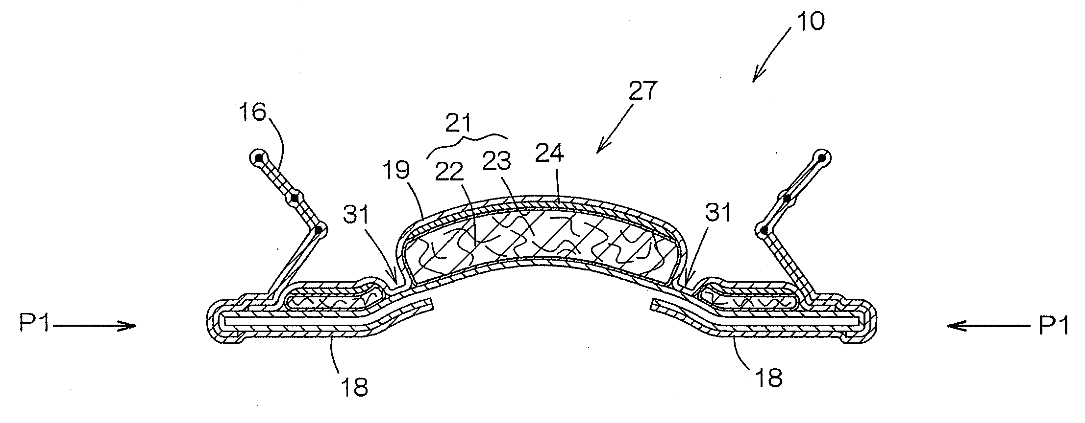
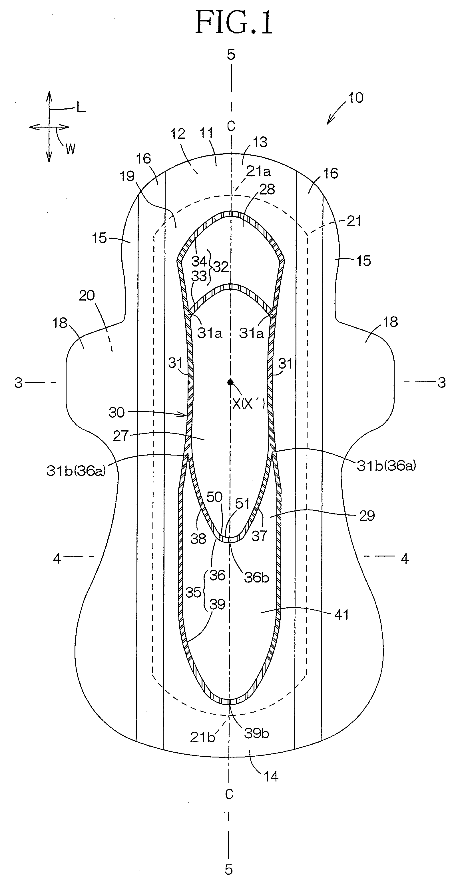
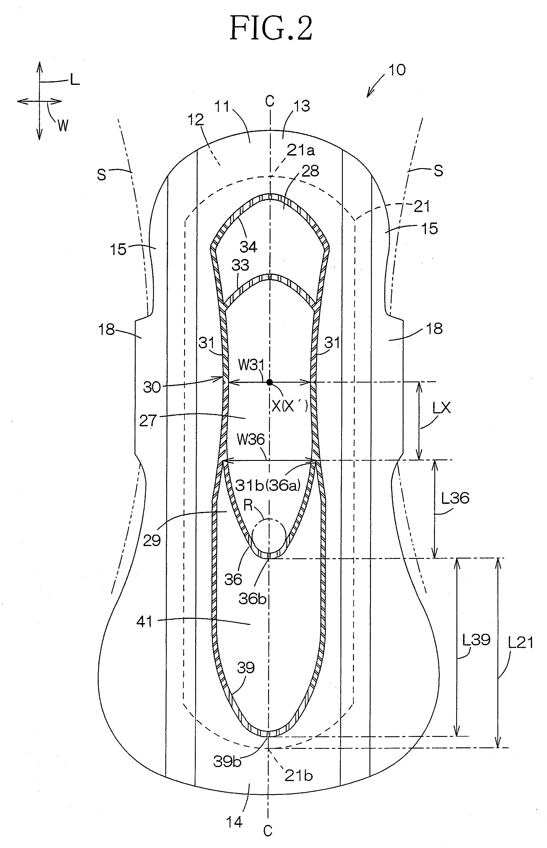
[0032]FIG. 1 is a plan view showing the sanitary napkin 10 with a body-side surface 11 facing upward. This napkin 10 is substantially in a flat state against a contractile force of elastic members 17 as will be described later. FIG. 2 is a plan view showing the napkin 10 with wings 18 as will be described later having been folded onto the rear surface and fastened to the wearer's shorts S. FIG. 3 is a sectional view of the napkin 10 taken along a line 3-3 in FIG. 1. FIG. 4 is a sectional view of the napkin 10 taken along a line 4-4 in FIG. 1. FIG. 5 is a sectional view of the napkin 10 taken along a line 5-5 in FIG. 1 defined by a longitudinal center line C of the napkin 10.

[0033] The napkin 10 is longer than is wide so as to be conveniently put on a men...


PUM


Abstract

An absorbent article includes a compressed groove provided on a body-side surface of a sanitary napkin includes a pair of lateral groove segments extending substantially in the longitudinal direction symmetrically about a longitudinal center line and a pair of rear groove segments converging rearward from respective rear ends of the pair of lateral groove segments so that the compressed groove as a whole presents an elongated shape which is angular rearward. The rear side groove segment has a curve conforming, in the vicinity of its rear end, with an arc of a circle having a predetermined radius and inscribed to the rear side groove segment. A bottom covering region extending rearward from the rear end of the rear groove segment has a predetermined thickness and is adapted to be folded along the longitudinal center line so that the bottom covering region can become convex on the side of the body-side surface. A distance between a pair of proximal ends of the rear side groove segment as measured in the transverse direction is in a predetermined range and a distance from the pair of proximal ends to the rear end of the rear groove segment as measured in the longitudinal direction is in a predetermined range.

Description

BACKGROUND OF THE INVENTION [0001] The present invention relates to an absorbent article and, more particularly, to an absorbent article such as sanitary napkin having an improved fit to the wearer' bottom. [0002] Japanese Unexamined Patent Application Publication No. 2001-8971 (hereinafter referred to as “REFERENCE”) discloses an absorbent article which is substantially longer than is wide, comprising an absorbent layer, a leak-barrier layer, a front region formed with one or two leak-barrier groove (s) extending in the longitudinal direction and a rear region formed with three or more leak-barrier grooves. In this article, sealing strength along the leak-barrier grooves is set to 50 cN / 30 mm or higher to prevent a possible leak of body fluids due to break and / or peeling off of a topsheet from an absorbent pad. [0003] However, in view of the fact that a zone extending behind the leak-barrier grooves has substantially the same thickness as the remaining zone, any effective and thoug...

Claims


Application Information

Patent Timeline
Patent Type & Authority Applications(United States)
IPC IPC(8): A61F13/15
CPCA61F13/4758A61F13/4704
Inventor NISHIKAWA, KUMIKOKUDO, JUNMIYAMA, TAKUYAHABU, CHIEMI
Owner UNI CHARM CORP
Why Eureka
Try Eureka