
Hybrid stent

a hybrid stent and stent technology, applied in the field of hybrid stents, can solve the problems of coil stents not being expandable, stents may not be able to properly anchor in the vessel, clots and fibrous masses which occlude,

Inactive Publication Date: 2007-01-04
STRYKER EURO OPERATIONS HLDG LLC +1
View PDF82 Cites 41 Cited by
  • Summary
  • Abstract
  • Description
  • Claims
  • Application Information

AI Technical Summary

Problems solved by technology

Open walled stents are believed to slow the blood flow in the aneurismal sac leading to the formation of clots and fibrous masses which occlude the aneurysm.
Typically, however, coil stents are not expandable.
If the size of the coil stent is not properly matched to the vessel, the stent may not be able to properly anchor in the vessel.

Method used


Image

  • Hybrid stent
  • Hybrid stent
  • Hybrid stent

Examples


Embodiment Construction

[0039] While this invention may be embodied in many different forms, there are described in detail herein specific preferred embodiments of the invention. This description is an exemplification of the principles of the invention and is not intended to limit the invention to the particular embodiments illustrated.

[0040] For the purposes of this disclosure, like reference numerals in the figures shall refer to like features unless otherwise indicated. Also for the purposes of this disclosure, the term “non-coil segment” shall be understood to mean a stent segment which is expandable mechanically, such as by balloon, self-expandable or otherwise expandable. Also, the term “coil segment” excludes segments which are in the form of a multiplicity of wires or strands which are woven or braided such as that disclosed in U.S. Pat. No. 5,061,275.

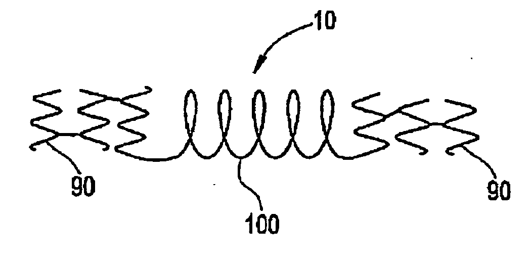
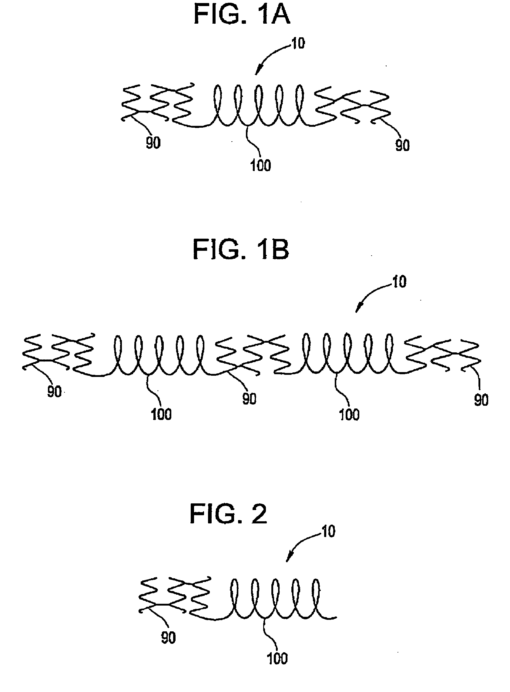
[0041] In one embodiment, the invention is directed to a stent such as that shown generally at 10 in FIG. 1a, comprising a plurality of segments, i...


PUM


Abstract

A stent comprises a plurality of segments, including at least one segment which is in the form of a coil and at least one segment which is in a form other than a coil and which is balloon expandable or self-expandable.

Description

BACKGROUND OF INVENTION [0001] The use of stents to maintain the patency of bodily lumens is well known. Stents are typically delivered via a catheter in an unexpanded configuration to a desired bodily location. Once at the desired bodily location, the stent is expanded and implanted in the bodily lumen. The stent may self-expand or may be mechanically expanded. Where a self-expanding stent is used, the stent is typically retained on the catheter via a retention device such as a sheath. The stent may be deployed by retracting the sheath from over the stent. Where a mechanically expandable stent is used, a radially outward force is typically applied to the stent to expand it. The force may be applied via an expandable member such as a balloon or via any other mechanical device. [0002] Stents are used in an array of bodily vessels including the coronary arteries, the peripheral arteries, arteries of the neck, cerebral arteries, veins, biliary ducts, urethras, ureters, fallopian tubes,...

Claims


Application Information

Patent Timeline
IPC IPC(8): A61F2/06A61F2/00A61F2/82A61F2/88
CPCA61F2/07A61F2/856A61F2/88A61F2/91A61F2002/065A61F2220/0058A61F2002/825A61F2250/0042A61F2250/0048A61F2220/005A61F2002/823
Inventor BERENSTEIN, ALEJANDROEDER, JOSEPH C.
Owner STRYKER EURO OPERATIONS HLDG LLC
Learn More