
Method and apparatus for analyzing twinned crystal

a twinned crystal and apparatus technology, applied in chemical methods analysis, material analysis using wave/particle radiation, instruments, etc., can solve problems such as difficult analytical operation

Inactive Publication Date: 2007-01-04
RIGAKU CORP
View PDF6 Cites 2 Cited by
  • Summary
  • Abstract
  • Description
  • Claims
  • Application Information

AI Technical Summary

Benefits of technology

[0009] It is an object of the present invention to provide a method and an apparatus for analyzing a twinned crystal with which even persons not familiar with crystallography can easily understand the relationship between the twin components and thus X-ray structural analysis of a twin crystal sample becomes more successful.
[0015] The twinned crystal analytical apparatus according to the present invention has an advantage that the real-space unit lattices, the reciprocal-space primitive lattices and diffraction spots (i.e., the reciprocal lattice points causing X-ray diffraction) of the twin components are displayed three-dimensionally with an alterable viewpoint based on the respective crystal orientation matrices of the twin components found by the X-ray single crystal structure analytical equipment, and thus persons not familiar with crystallography can understand the relationship between the twin components, especially the degree of overlap of the reciprocal lattice points. Accordingly, interpreting and analyzing observed diffraction spots can be carried out in consideration of the three-dimensional relationship between the twin components, so that X-ray structural analysis of a twin crystal sample becomes more successful.

Problems solved by technology

In the twinned crystal case, however, an analytical operation would be difficult because of overlap of the diffraction spots as compared with the ordinary single crystal.

Method used


Image

  • Method and apparatus for analyzing twinned crystal
  • Method and apparatus for analyzing twinned crystal
  • Method and apparatus for analyzing twinned crystal

Examples


Embodiment Construction

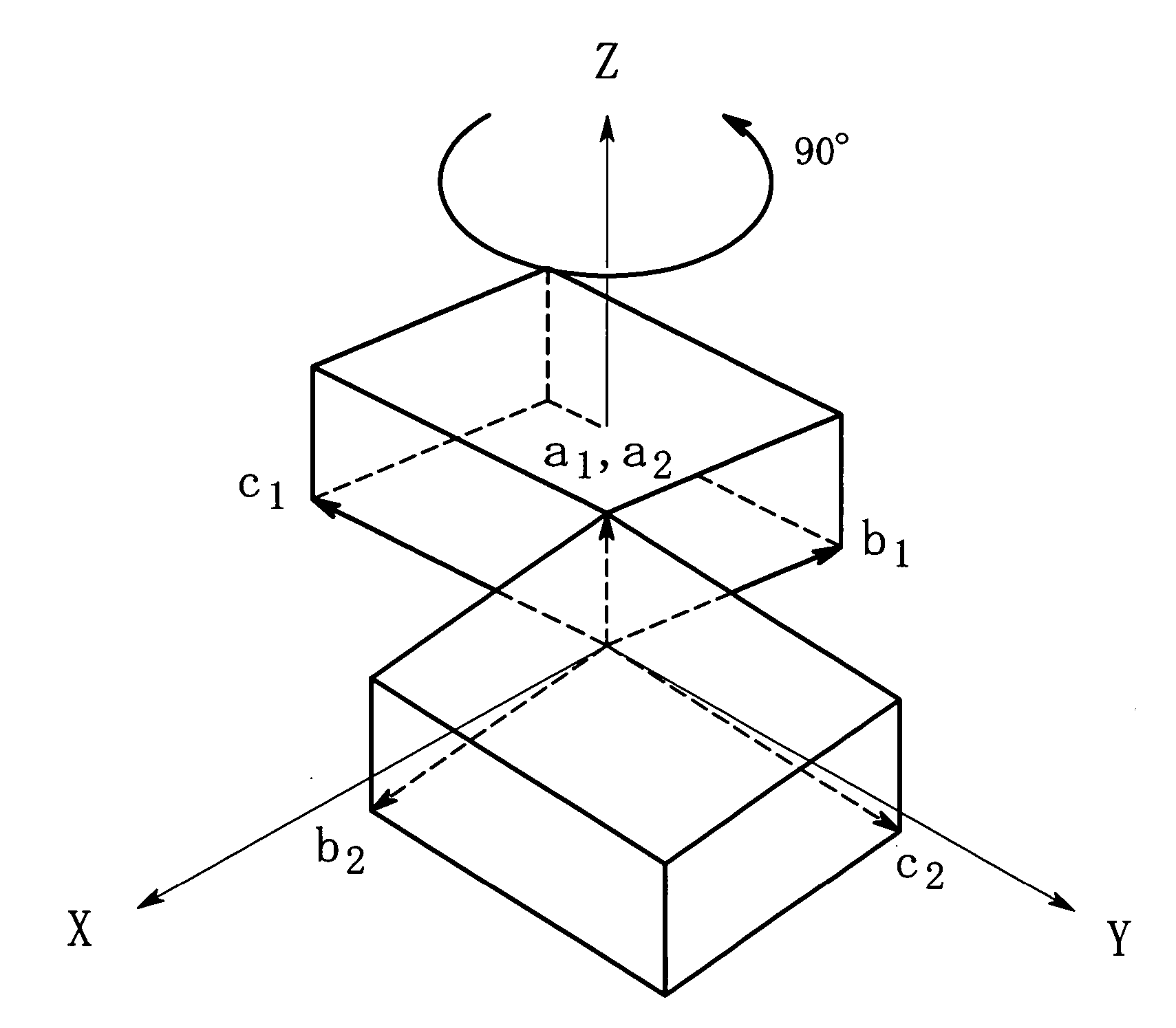
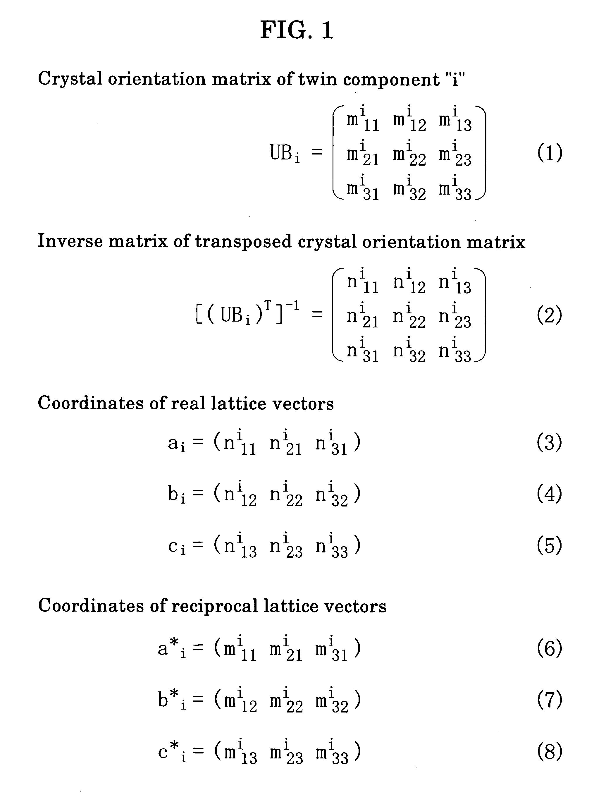
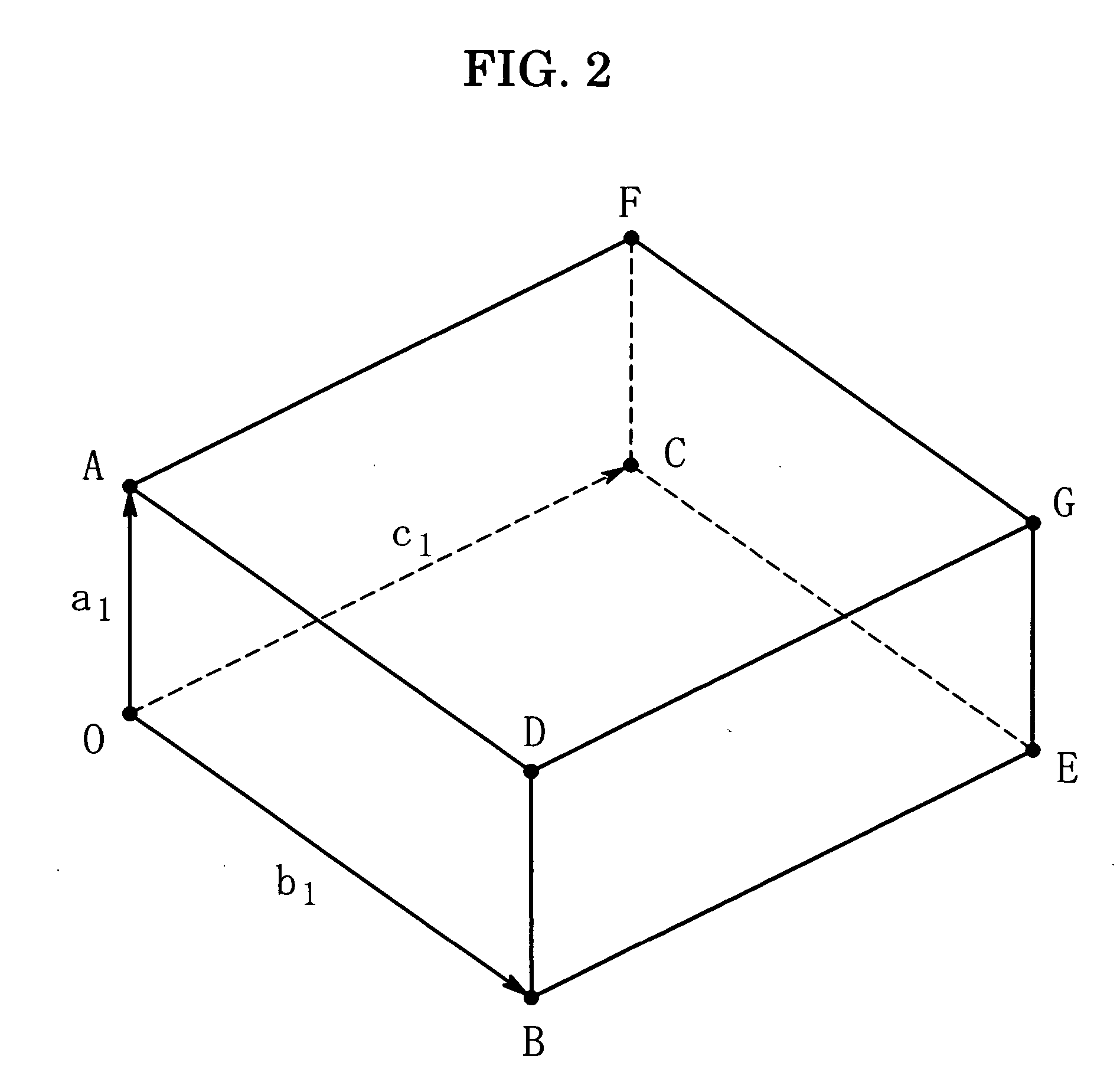
[0040] Embodiments of the present invention will now be described in detail below with reference to the drawings. First of all, there will be explained a method of depicting real-space unit lattices and reciprocal-space primitive lattices based on the crystal orientation matrices, provided that the respective crystal orientation matrices of the plural components of a twinned crystal are known. The crystal orientation matrix UBi of a twin component “i” is expressed by a three-row, three-column matrix as shown in equation (1) in FIG. 1. A twinned crystal sample consisting of two components has two crystal orientation matrices, i.e., i=1 and i=2. The inverse matrix of the transposed crystal orientation matrix is expressed by equation (2) in FIG. 1. The unit lattice in real space (i.e., real-space unit lattice) of the twin component “i” is expressed by a set of the real lattice vectors and the coordinates of the real lattice vectors are expressed by equations (3) thorough (5) in FIG. 1....


PUM

PropertyMeasurementUnit
crystal orientationaaaaaaaaaa
reciprocal lattice pointsaaaaaaaaaa
reciprocal latticeaaaaaaaaaa

Abstract

A method and an apparatus for analyzing a twinned crystal can display three-dimensionally the real space unit lattice, the reciprocal space primitive lattices and the reciprocal lattice points of each component of the twinned crystal. Respective crystal orientation matrices of the plural components of the twinned crystal are obtained with the use of X-ray single crystal structure analytical equipment. The first computing means finds the real-space unit lattices of the plural components based on the crystal orientation matrices and creates display data for displaying them three-dimensionally with possible their rotation, scaling up and down and translation. The second computing means finds the reciprocal-space primitive lattices and creates display data for displaying them three-dimensionally. The third computing means creates display data for displaying three-dimensionally reciprocal lattice points causing X-ray diffraction with a distinction between the components of the twinned crystal.

Description

BACKGROUND OF THE INVENTION [0001] 1. Field of the Invention [0002] The present invention relates to a method and an apparatus for analyzing a twinned crystal with the use of X-ray single crystal structure analytical equipment using an X-ray diffraction method and for displaying the analytical result three-dimensionally. [0003] 2. Description of the Related Art [0004] Single crystal structure analysis using the X-ray diffraction method requires high-accurate measurement of intensities of diffraction spots which are recorded in an X-ray detector. If a sample is a single crystal, it is easy to determine diffraction spot intensities with a high accuracy with the use of the ordinary X-ray single crystal structure analytical equipment. On the other hand, when a sample is a twinned crystal, especially when classified to non-merohedral twin, appearance of diffraction spots depends upon the geometrical relationship between the twin components, resulting in that, on the X-ray detector, diffr...

Claims


Application Information

Patent Timeline
Patent Type & Authority Applications(United States)
IPC IPC(8): G06F19/00G01N23/20
CPCG01N23/2055
Inventor HIGASHI, TSUNEYUKI
Owner RIGAKU CORP
Learn More