
Heat retaining wetsuit

Inactive Publication Date: 2007-01-11
SHEI CHUNG HSIN IND
View PDF8 Cites 5 Cited by
  • Summary
  • Abstract
  • Description
  • Claims
  • Application Information

AI Technical Summary

Benefits of technology

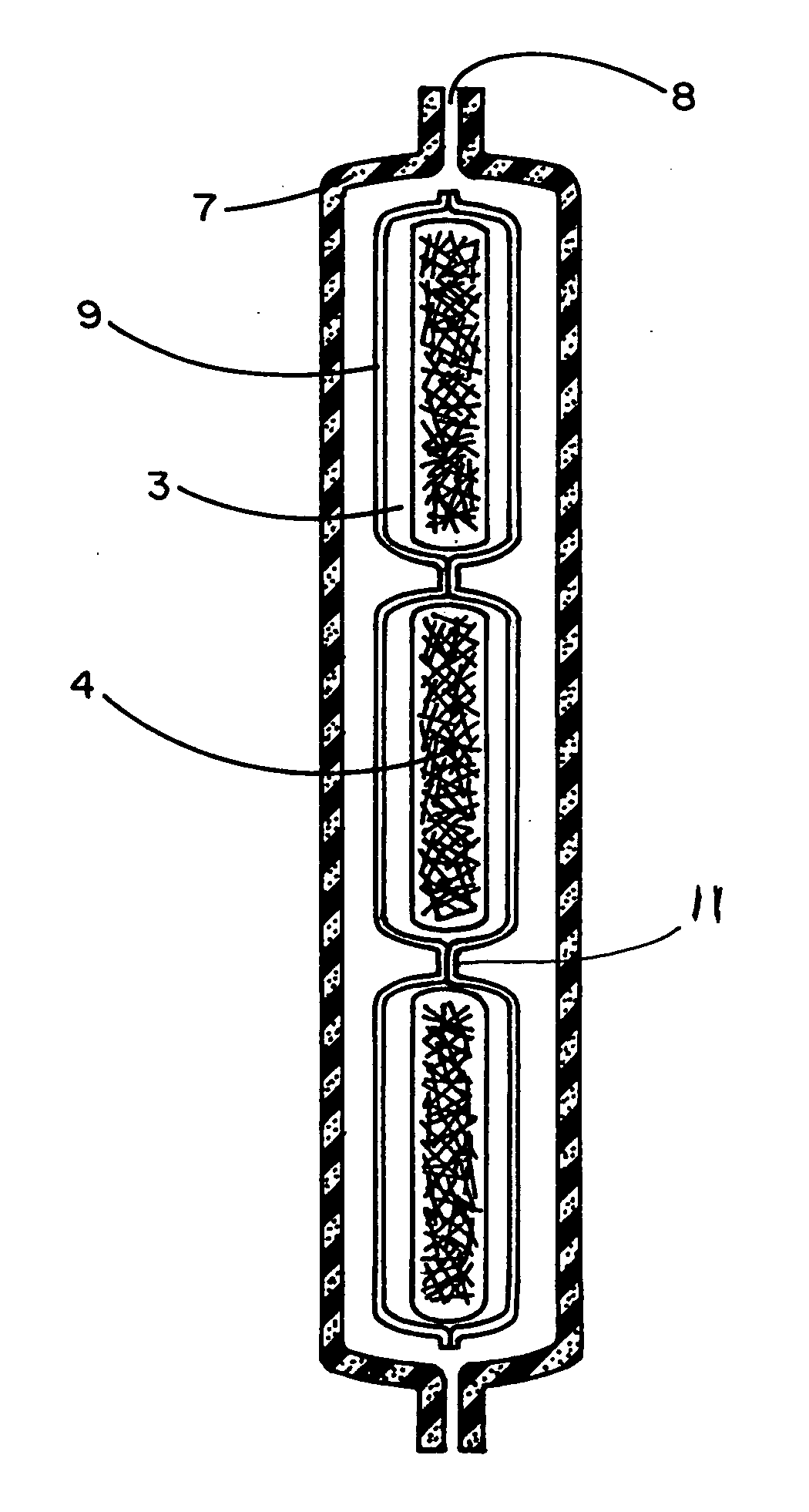
[0009] The present invention comprises a wetsuit and wetsuit fabric made of a multi-layer laminated sponge material having a plurality of air chambers formed between the sponge layers. The air chambers are formed by unattached regions between sponge layers that are otherwise attached such as by gluing. The unattached regions are free to separate from each other and expand in response to receiving low density stuffing material. Using the stuffing material to hold and increase the amount of air in the Air Chamber reduces the rate of temperature conduction of the water, thereby slowing down thermal loss of the wearer's body. The stuffing material is light with a density of 0.02˜0.05 mg / cm3, and of multi-layered fiber structure and the like. The Air Chamber can be located at any part of the wetsuit, but is normally on the breast or back and the selected portion when used, provides the person who wears the wetsuit the function of heat retaining / thermal insulation and impact protection.
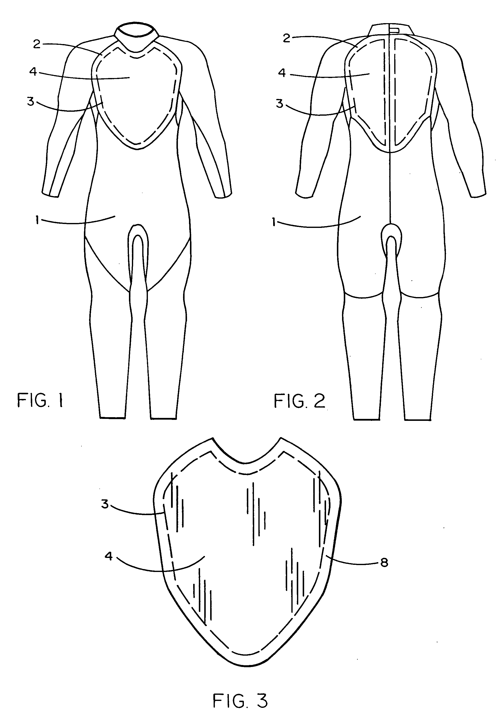
[0010] In the embodiment described herein, these chambers are of a selected shape, however, it will be understood that these chambers may be virtually any shape depending simply on the design chosen for the air chambers. The disclosed embodiment illustrates application of the invention in the front and back chest area of a wetsuit. However, it will also be understood that sponge material employing expandable air chambers may be employed at virtually any location in a wetsuit as well as in accessories such as gloves, boots and hoods. Irrespective of their shape and location, the expandable air chambers within the layers of a wetsuit sponge, provide increased thermal insulation, improved impact protection and a new aesthetic effect in the wetsuit design. All of these advantages are achieved without substantially complicating the manufacture of the wetsuit fabric by simply controlling the application of glue between the sponge layers such as by embossing the glue in a selected pattern before joining the layers and placing very low density material between the sponges where no glue has been applied.

Problems solved by technology

Such prior art tends to be either very cumbersome, or irreversible and generally does nothing to add to the aesthetic appearance of the wetsuit.

Method used


Image

  • Heat retaining wetsuit
  • Heat retaining wetsuit
  • Heat retaining wetsuit

Examples


Embodiment Construction

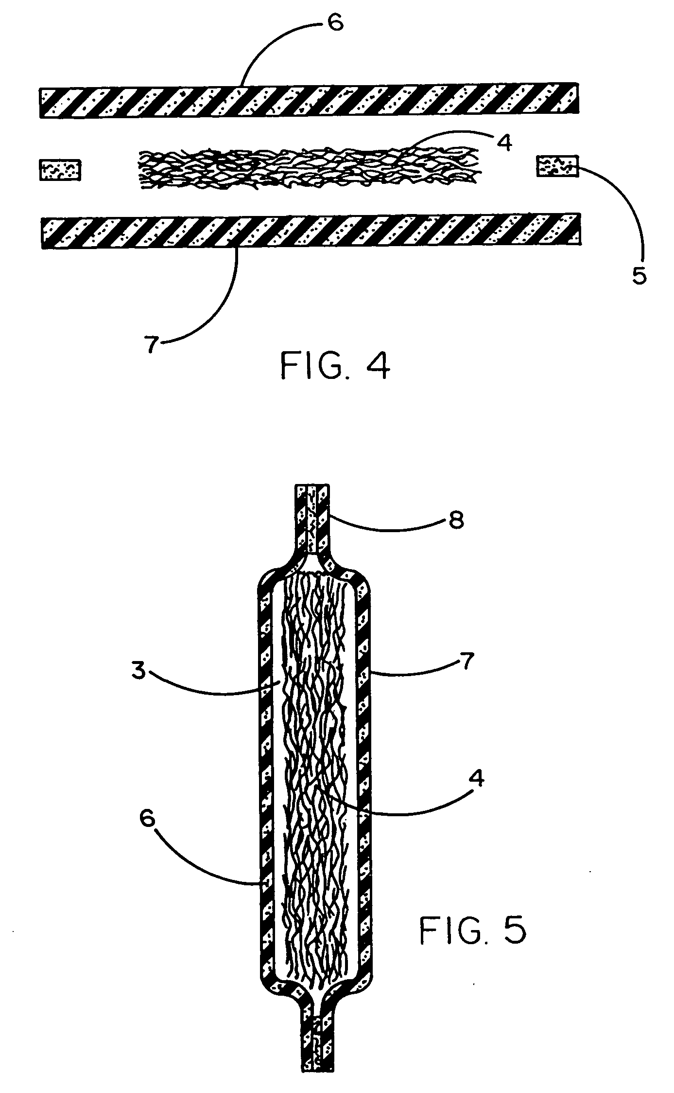
[0021] Referring to the accompanying drawings, it will be seen in FIGS. 1 through 5 that in a preferred embodiment of the present invention, a wetsuit comprises two layers of a sponge-like material, namely, layer 6 and layer 7. These sponge layers may or may not have a fabric-covered surface. In the wetsuit 1 shown in FIG. 1, most of the regions of the two layers of sponge material are glued together using glue 5 to form a laminated wetsuit configuration. However, in one or more selected regions 2 (i.e., chest, left back, right back, etc.) the two layers of sponge material are left unglued and thus free to separate from one another to form an air chamber 3 surrounded by a glued border 8.

[0022] In the preferred embodiment shown herein, these air chambers are filled with a low density stuffing material 4. This material will preferably have a density of 0.02˜0.05 mg / cm3 such as can be achieved using a multi-layered fiber structure (i.e., layered cotton fiber, synthetic fiber or the li...


PUM


Abstract

A wetsuit comprised of two layers of laminated rubber sponge material which may or may not be fabric coated. A stuffing material of variable thickness is located in selected areas between the two rubber sponges referred to herein as Air Chambers. The two layers of laminated rubber sponges are glued together along their adjacent surfaces except in selected areas where their common borders of the sponges are left unglued and form a watertight construction, i.e., the “Air Chamber”. The stuffing material is a light material with a density of 0.02˜0.05 mg / cm3 and typically formed of multi-layered fiber structure and the like. The Air Chamber can be located at any part of the wetsuit to provide the person who wears the wetsuit the function of heat retaining / thermal insulation and impact protection. In an additional embodiment, the stuffing material is secured within another thin plastic enclosure within the air chamber. This enclosure may be provided as a single pocket or as a plurality of contiguous pockets.

Description

CROSS-REFERENCE TO RELATED APPLICATIONS [0001] This application is a continuation-in-part of application Ser. No. 11 / 174,688 filed Jul. 5, 2005.BACKGROUND OF THE INVENTION [0002] 1. Field of the Invention [0003] The present invention relates generally to the field of wetsuits used for diving, surfing and the like, and more specifically to an improved wetsuit comprising two layers of laminated rubber sponge material which may or may not be coated with fabric and a stuffing material of variable thickness, between the two rubber sponges. [0004] The two layers of laminated rubber sponge material are glued at the borders of the sponges and form a water-tight construction, called an “Air Chamber”. Using the stuffing material to hold and increase the amount of air in the Air Chamber reduces the rate of temperature conduction of the water, thereby slowing down thermal loss of the wearer's body. The stuffing material is light with a density of 0.02˜0.05 mg / cm3, and a multi-layered fiber stru...

Claims


Application Information

Patent Timeline
IPC IPC(8): A41D1/14
CPCA41D31/0038B63C11/04A41D2400/14A41D13/012A41D13/015A41D31/065
Inventor SHIUE, MIN-CHEN
Owner SHEI CHUNG HSIN IND
Learn More