Piano dolly

a technology for pianos and dolly wheels, applied in the field of dolly wheels, can solve the problems of pedal lyres precluding the use the design of spider dolly wheels does not lend itself to pre-assembly before shipping, and the pedal lyres are difficult to make in advance, so as to reduce the weight and eliminate the central hub. the effect of the us

Inactive Publication Date: 2007-01-11
GRK MFG
View PDF16 Cites 7 Cited by
  • Summary
  • Abstract
  • Description
  • Claims
  • Application Information

AI Technical Summary

Benefits of technology

[0014] The various embodiments of the present invention can provide one or more of the following advantages. The lack of the central hub used by conventional spider dollies coupled with the use of a single pivot to interconnect the first and second legs of the dolly of the present invention, as compared to the use of three separate legs each pivotally coupled to the central hub of conventional spider dollies, significantly reduces the complexity of adjusting the piano dolly of the present invention to fit the shape and size of a particular piano, as compared to the adjustments required when using a conventional spider dolly. Part of this simplification is achieved by mounting two of the flanged cups to the first leg of the dolly along a straight line, with each of the cups being effective for receiving a caster mounted to one of the legs of the piano. In view of the foregoing simplification, the amount of assembly that can be achieved prior to shipping is increased relative to that which can typically be done with conventional spider dollies, such that the installation of the piano dolly of the present invention at the point of use is simpler.
[0015] The elimination of the central hub of the conventional spider dollies also provides the following advantages. In the first instance, a significant weight reduction is achieved, which is estimated to be about 15% reduction in weight as compared to conventional spider dollies accommodating pianos of like size and weight. Furthermore, elimination of the central hub used with conventional spider dollies, eliminates the potential problem of interference with a pedal lyre mounted to the piano. Accordingly, the piano dolly of the present invention can be used with relatively smaller grand pianos, having pedal lyres, whereas conventional spider dollies typically cannot.
[0016] The simpler and less complex design of the piano dolly of the present invention, as compared to conventional spider dollies, also results in fewer parts, and therefore less weight and less cost, both with regard to parts cost and shipping cost. The simpler design is also aesthetically more pleasing, as it is more streamlined as compared to conventional spider dollies, and therefore will detract less from the aesthetic beauty of the pianos which they support.

Problems solved by technology

For example, the design of a typical spider dolly does not lend itself to pre-assembly before shipping.
These angular and length adjustments are very difficult to make in advance.
For smaller pianos of this type, the location of the pedal lyre can preclude the use of a spider dolly due to interference between the lyre and the central hub of the dolly.
Another disadvantage with spider dollies is that they are sometimes considered to be somewhat unsightly and can detract from the aesthetic beauty of the piano.
This can be particularly problematic in some circumstances.
In instances such as this, the unattractive visual appearance of a spider dolly is undesirable.
Additionally, the central hub and number of component parts are heavier and more costly, both with regard to part cost and shipping cost, than the simpler design provided by the dolly of the present invention.

Method used


Image

  • Piano dolly
  • Piano dolly
  • Piano dolly

Examples


Embodiment Construction

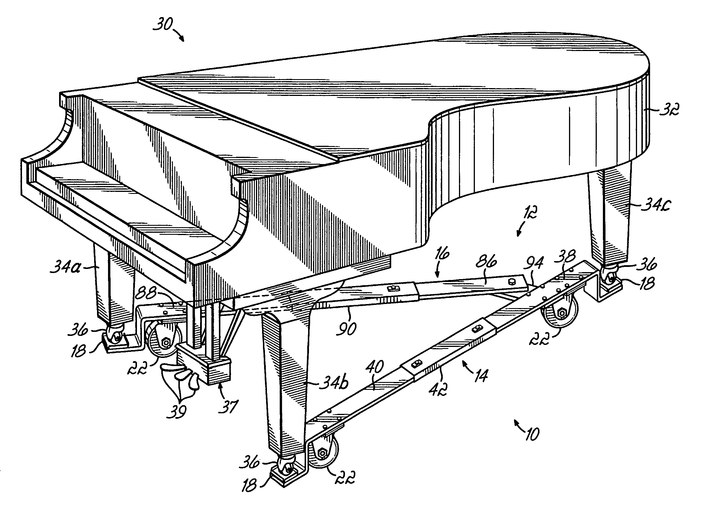
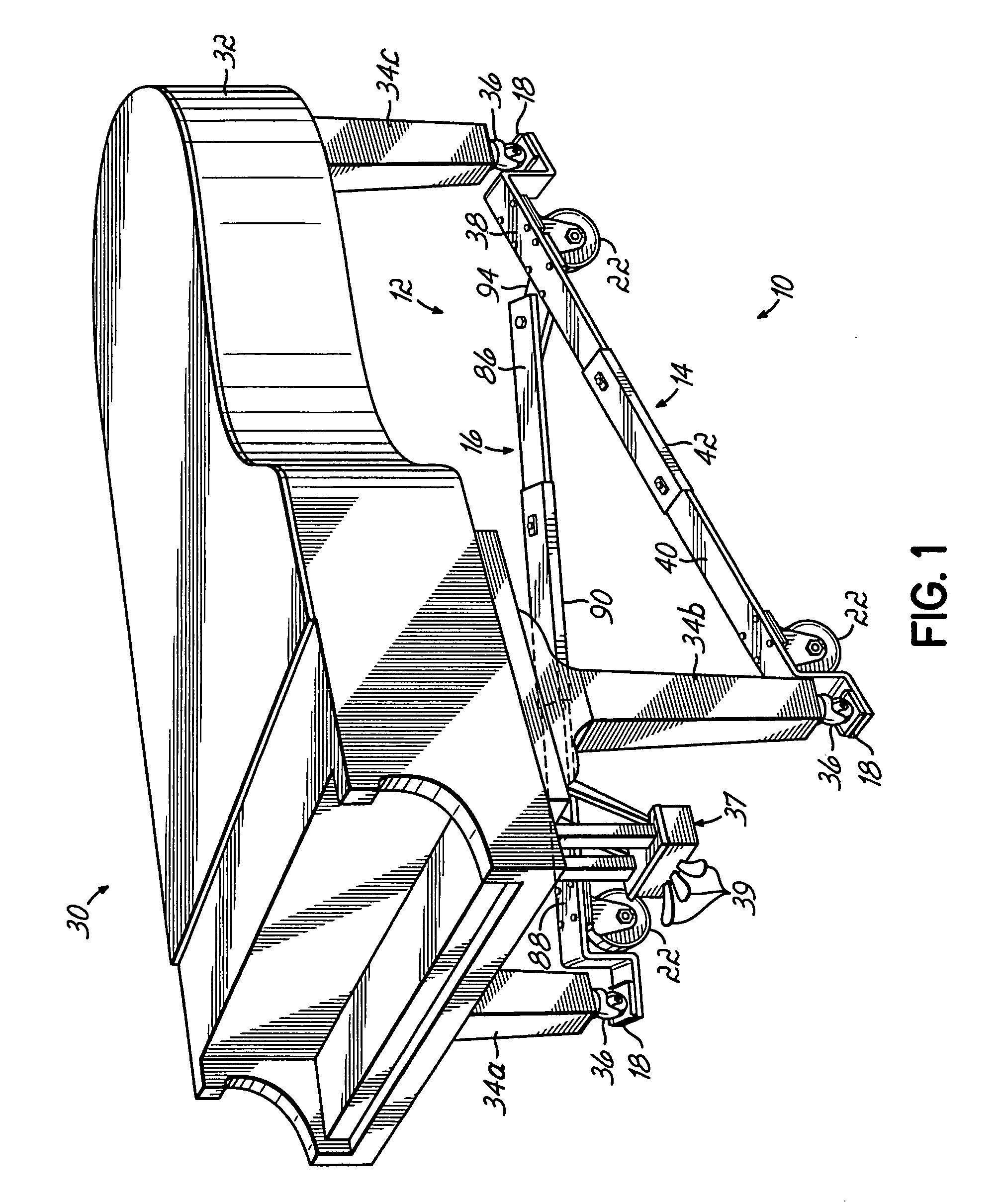
[0025] Referring now to the drawings, FIG. 1 is a perspective view illustrating a dolly 10 according to one embodiment of the present invention. The dolly 10 has a base 12 that includes first 14 and second 16 legs. The second leg 16 is pivotally coupled to the first leg 14, for rotation relative to the first leg 14. The dolly 10 further includes a plurality of receptacles 18 mounted to the base 12. As shown in FIG. 1, two of the receptacles 18 are mounted to the first leg 14 and are spaced apart from one another along a longitudinal centerline 20 (shown in FIG. 3) of the first leg 14. The third one of the receptacles 18 is mounted to the second leg 16. Dolly 10 further includes a plurality of conventional casters 22 mounted to the base 12 and operatively effective for rolling along a surface (not shown). Each of the casters 22 is preferably a swiveling-type caster, with each of the casters 22 including a wheel 24, rotatable about a horizontal axis (not shown) passing through the cen...


PUM


Abstract

A dolly for moving a piano is provided and includes a base having first and second legs, with the first leg having a longitudinal centerline and the second leg being pivotally coupled to the first leg for rotation relative to the first leg. A plurality of receptacles are mounted to the base, with each of the receptacles being operatively effective for receiving a castor mounted to a leg of the piano. First and second ones of the receptacles are mounted to the first leg and spaced apart from one another along the longitudinal centerline of the first leg, with a third one of the receptacles being mounted to the second leg. A plurality of castors are mounted to the base and are operatively effective for rolling along a surface.

Description

FIELD OF THE INVENTION [0001] The present invention relates to a dolly, and more particularly, to a dolly for moving a piano from one location to another. BACKGROUND OF THE INVENTION [0002] Piano dollies are well known in the art and are used to move pianos to and from the place of use, such as the stage of an auditorium, opera house or the like. Known dollies include those which can be used to support and move grand pianos, having three legs. Dollies of this type, which are sometimes referred to as “spider dollies”, typically have a central hub formed from two vertically spaced plates, and three legs extending radially outwardly from between the plates. Each leg is pivotally mounted at its inner end to the central hub so that each leg may be rotated relative to the hub to accommodate pianos of different shapes. To provide further adjustability, each of the three legs of known spider dollies are typically adjustable in length. [0003] The distal ends of the legs of known spider dolli...

Claims


Application Information

Patent Timeline
Patent Type & Authority Applications(United States)
IPC IPC(8): B62B3/02
CPCB62B5/0083G10G7/005G10C3/00B62B2202/34G10C1/04
Inventor KILDAY, GARY R.PRITT, MICHAEL W.
Owner GRK MFG
Why Eureka
Try Eureka