Folding leg brace for a wheelbarrow

a leg brace and wheelbarrow technology, applied in the field of wheelbarrows, can solve the problem of limited number of components and achieve the effect of wide profil

Inactive Publication Date: 2007-01-11
AMES TRUE TEMPER
View PDF10 Cites 14 Cited by
  • Summary
  • Abstract
  • Description
  • Claims
  • Application Information

AI Technical Summary

Benefits of technology

[0012] The first and second leg assemblies are further coupled to an adjustable brace assembly. The adjustable brace assembly has a first member and a second member. The adjustable brace assembly first member and second member are each an elongated member having a first end, a second end, and a medial portion. The first and second members are pivotally coupled to each other at the medial portion, thereby forming a scissor-like assembly. The first and second members are structured to move between a first configuration and a second configuration relative to each other. In the first configuration, the first and second members almost overlap each other in a first direction, thereby having a narrow profile. In the second configuration, the first and second members are rotated to almost overlap each other in a second direction, thereby having a wide profile.

Problems solved by technology

Thus, when the frame assembly is removed from a container, a user is required to attach a limited number of components as much of the frame assembly is already assembled.

Method used


Image

  • Folding leg brace for a wheelbarrow
  • Folding leg brace for a wheelbarrow
  • Folding leg brace for a wheelbarrow

Examples


Embodiment Construction

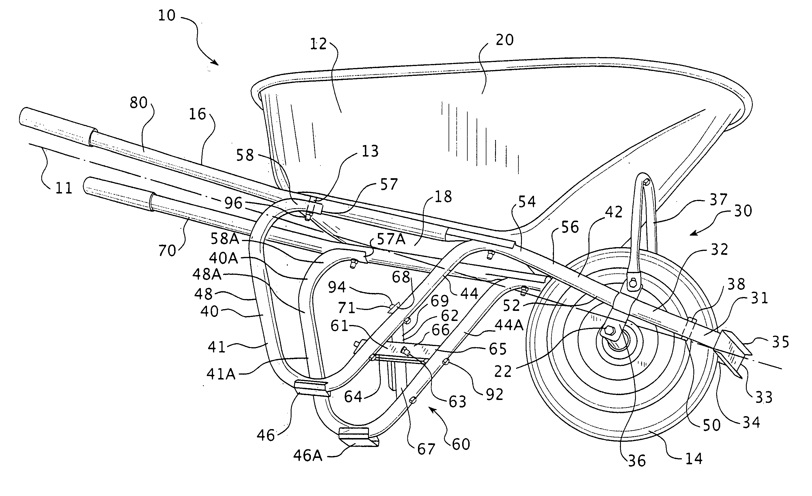
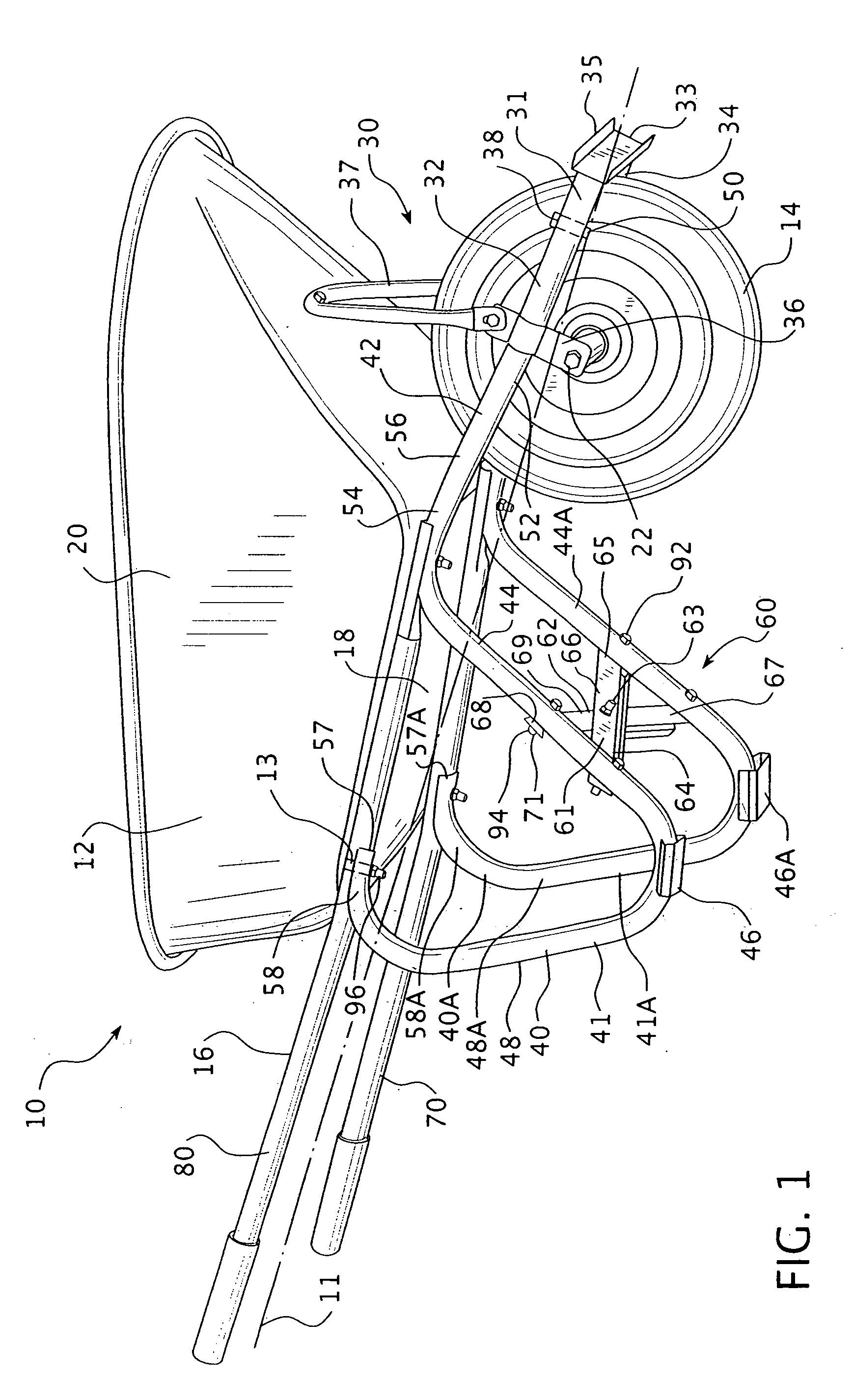
[0017] As shown in FIG. 1, a wheelbarrow 10 includes a hopper 12, a wheel 14 and a frame assembly 16. The wheelbarrow 10 is generally symmetrical about a longitudinal centerline 11. The hopper 12 includes a generally flat base plate 18 having a depending, flared peripheral sidewall 20. The hopper base plate 18 includes a plurality of fastener openings 13. The wheel 14 includes an axle 22 structured to be attached to the frame assembly 16.

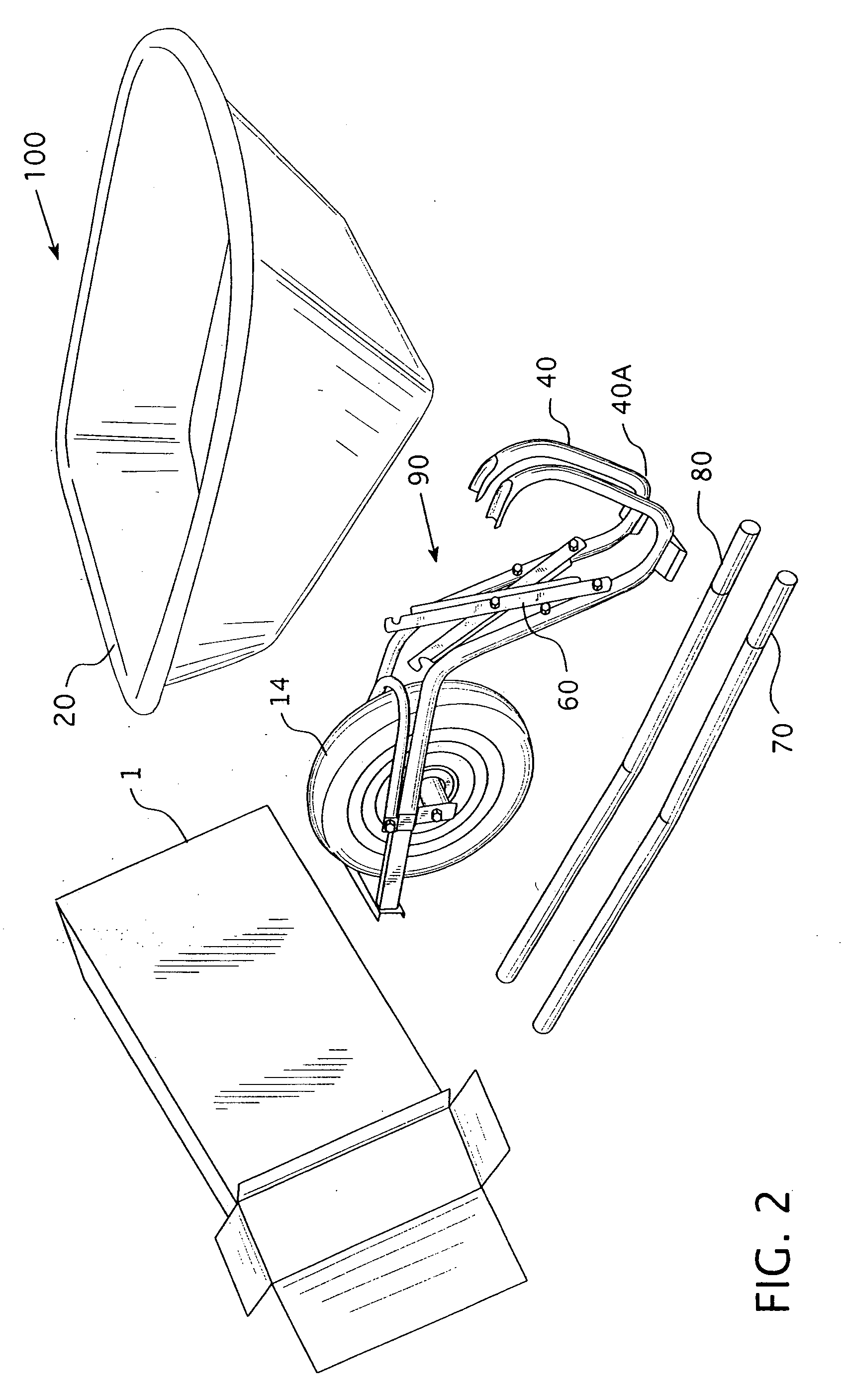
[0018] The frame assembly 16 includes a wheel brace assembly 30, a first adjustable leg assembly 40, a second adjustable leg assembly 40A, an adjustable brace assembly 60, a first handle member 70 and a second handle member 80. The wheel brace assembly 30 includes a frame assembly 31 having a first tine member 32, a flat bight member 33, a second tine member 34, a bight guard 35, two wheel brackets 36, and a hopper support 37. Each tine member 32, 34 also has two opposing pivot pin openings 38 disposed adjacent to the distal end of each tine member...


PUM


Abstract

The present invention provides a wheelbarrow having a collapsible frame assembly. The wheelbarrow also includes a hopper and a wheel. The frame assembly includes a wheel brace assembly, a first adjustable leg assembly, a second adjustable leg assembly, a first handle member and a second handle member. The wheel brace assembly is narrow relative to the hopper. The first adjustable leg assembly and the second adjustable leg assembly are pivotally coupled to the wheel brace assembly. The first and second leg assemblies are each structured to move between a first configuration and a second configuration. In the first configuration, the first and second leg assemblies are structured to be closer to the centerline of the wheelbarrow, and/or frame assembly, so that the width of the legs/brace sub-assembly is relatively narrow.

Description

CROSS SECTION TO RELATED APPLICATION [0001] This application claims priority under 35 U.S.C. §119(e) to U.S. Provisional Patent Application Ser. No. 60 / 696,577, filed Jul. 5, 2005, entitled, FOLDING LEG BRACE FOR A WHEELBARROW.BACKGROUND OF THE INVENTION [0002] 1. Field of the Invention [0003] This invention relates to wheelbarrows and, more specifically, a wheelbarrow having a scissor-like leg brace structured to reduce the time and effort required to assemble the wheelbarrow. [0004] 2. Background Information [0005] Wheelbarrows are well known in the art. Typically, a wheelbarrow included a hopper and a frame assembly having a curved yoke, a wheel, and a brace. The yoke included two elongated members typically joined by a nose guard at the forward most point. The elongated members were shaped to have a portion that curved downwardly to form a footpad and then curved upwardly to form handles. The hopper rested on, or in between, a medial portion of the yoke members. The wheel was di...

Claims


Application Information

Patent Timeline
Patent Type & Authority Applications(United States)
IPC IPC(8): B62B1/00
CPCB62B1/206
Inventor ALBERT, BARRY
Owner AMES TRUE TEMPER
Why Eureka
Try Eureka