Adjustable towing hitch assembly

a towing hitch and adjustable technology, applied in the field of towing, can solve the problems of affecting the rigidity of the apparatus, and the complexity of the apparatus is relatively high

Inactive Publication Date: 2008-06-05
COQUENT TOWING PRODS
View PDF20 Cites 6 Cited by
  • Summary
  • Abstract
  • Description
  • Claims
  • Application Information

AI Technical Summary

Benefits of technology

[0007]Specifically, the trailer hitch receiver includes selectively positionable mounting flanges and mounting brackets adapted to provide enhanced versatility when mounting the trailer hitch receiver to the frame of a towing vehicle. Further, these flanges and brackets are relatively low profile, single-piece components that are relatively inexpensive to manufacture and easy to use. Unlike conventional telescoping tubular components that have a relatively wide profile, these mounting brackets provide the necessary clearance to fit in tight areas around vehicle components and, as such, are more functional and suited to many more applications. While allowing the necessary adjustability, the flanges and brackets also insure a rigid connection.
[0008]Advantageously, the flanges may be positioned at substantially any point along the length of the cross member of the receiver. Accordingly, the spacing between the flanges may be adjusted to provide a customized fit with the frame of the vehicle to which the receiver is mounted. As a result, one receiver is capable of being mounted to more makes and models of vehicles. The brackets of the receiver may also be selectively positioned fore or aft, up or down, and inboard or outboard to provide relative adjustment in several directions. In addition, the cross member being engaged telescopingly engaged with the first and second extension tube further provide adjustability. This ability provides substantial versatility and allows the mounting of the trailer hitch assembly to a wider range of vehicles.
[0010]To achieve the foregoing and other objects, and in accordance with the purposes of the present invention as described herein, the receiver assembly comprises first and second mounting brackets removably attachable to first and second mounting flanges. The first and second mounting flanges are removably attached to first and second extension tubes respectively. A cross member is telescopically received within the extension tubes at either end thereof. The first and second mounting brackets include a set of mounting apertures. The first and second mounting flanges include a set of anchoring apertures. The first and second mounting brackets are removably attachable to the first and second mounting flanges in a variety of positions. Fasteners are attached a portion of said set of mounting apertures and a portion of said set of anchoring apertures to adjustably attach said mounting flanges and mounting brackets. This permits said receiver assembly to be positionable in different up and down (or vertical) positions and different fore and aft positions. Additionally, the first and second extension tubes with the cross member allows for additional adjustability of said receiver assembly.

Problems solved by technology

The apparatus is, however, relatively complicated and includes a number of parts to allow adjustability while providing for the mounting of the main frame member.
Further, a conventional telescoping tubular construction is used and this introduces substantial play into the arrangement resulting in a detrimental loss in rigidity.

Method used


Image

  • Adjustable towing hitch assembly
  • Adjustable towing hitch assembly
  • Adjustable towing hitch assembly

Examples


Embodiment Construction

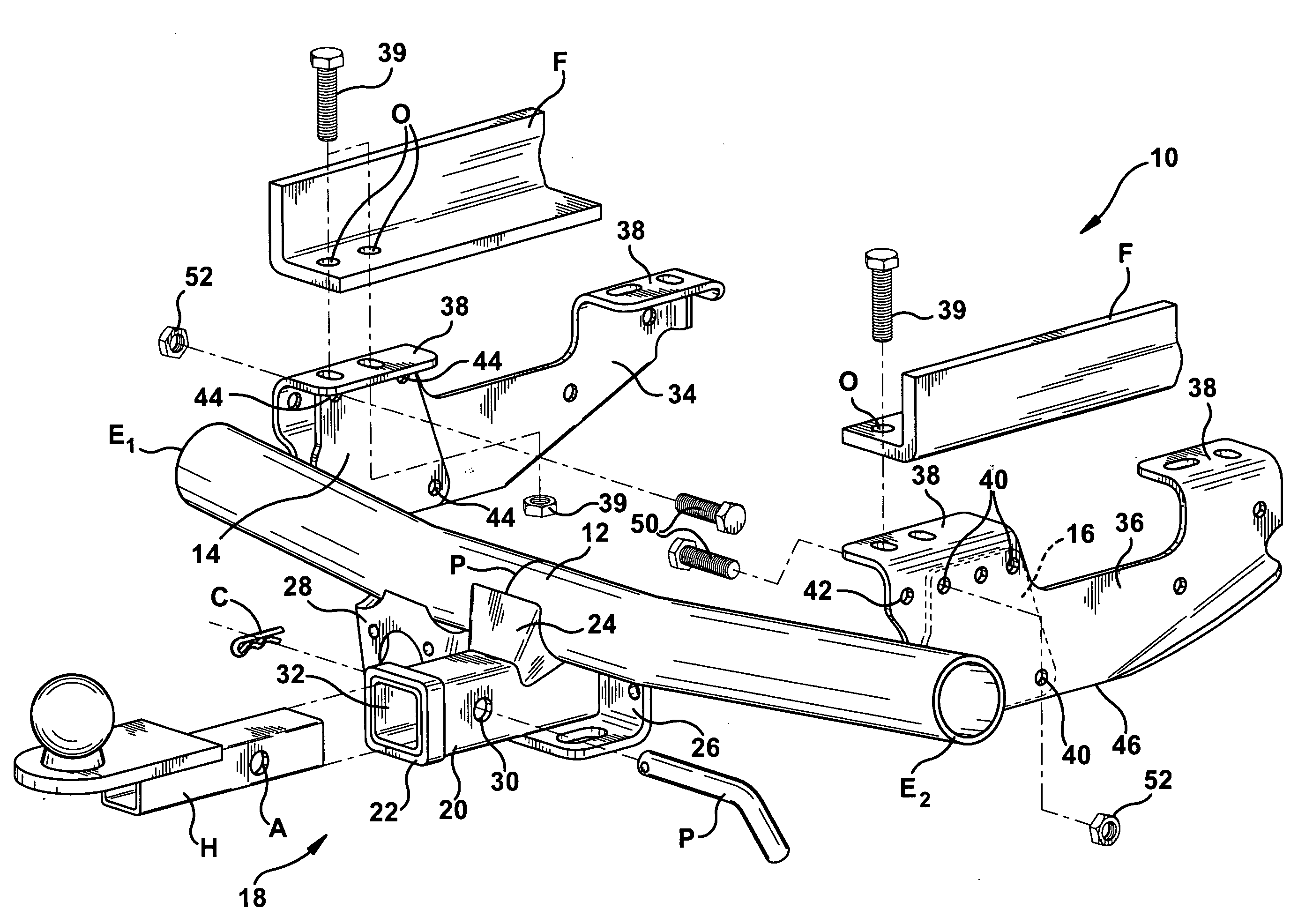
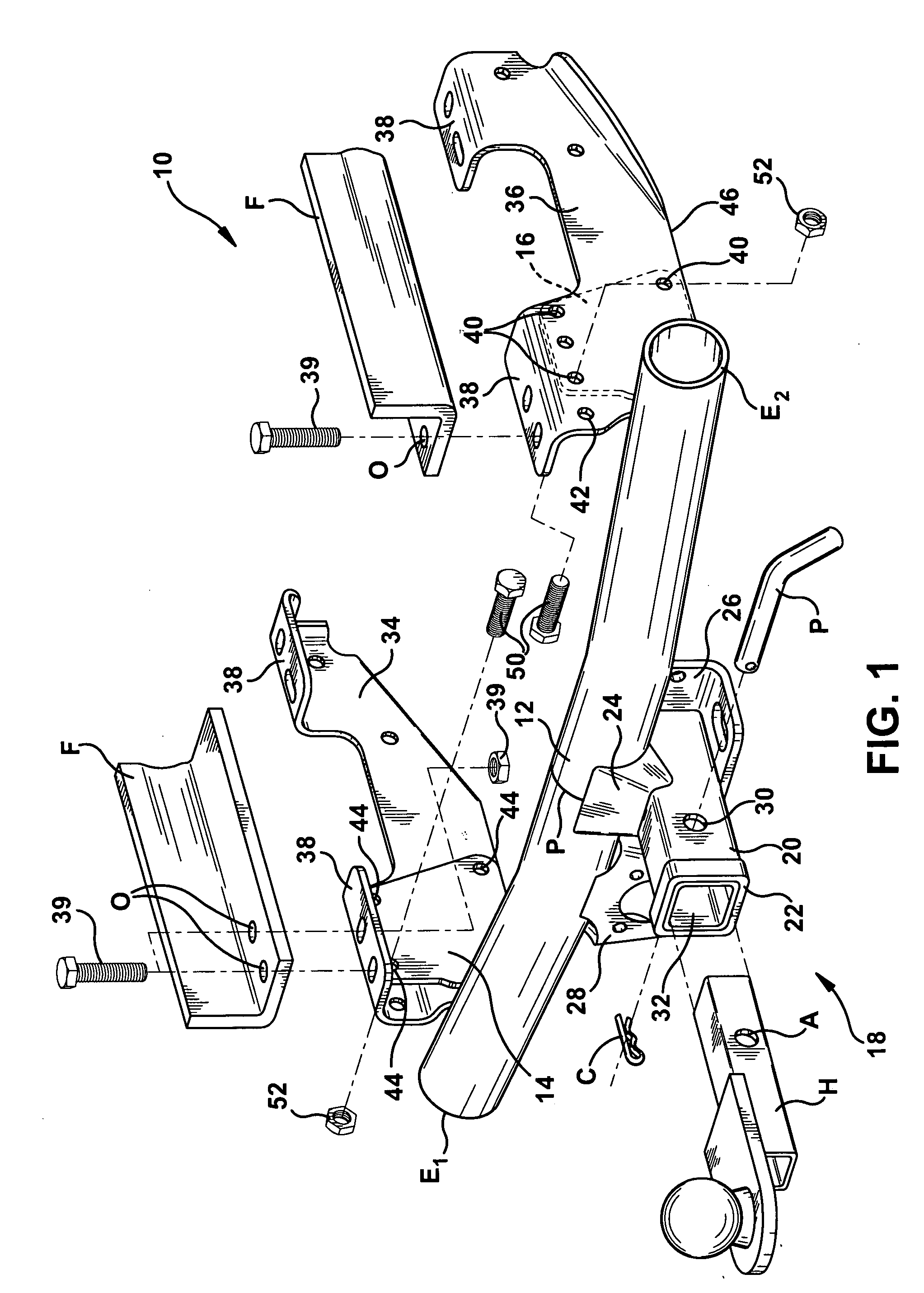
[0021]Reference is now made to FIG. 1 showing the trailer hitch receiver 10 of the present invention. The trailer hitch receiver 10 includes a main frame member 11 preferably formed from tubular steel material. As clearly illustrated, the main frame member 11 includes a cross member 12 that may have a round cross section. The cross member 12 includes a first end E1, and a second end E2, and a midpoint P.

[0022]A first selectively positionable mounting flange 14 is secured to the cross member 12 at a selected first point between the first end E1 and the midpoint P of the cross member 12. Similarly, a second mounting flange 16 is secured to the cross member 12 at a selected point between the second end point E2 and the midpoint P of the cross member 12. Advantageously, by altering or adjusting the positioning of the two flanges 14, 16 along the cross member 12, the spacing between them may be varied to provide a custom fit with the frame of substantially any towing vehicle.

[0023]Each m...


PUM


Abstract

Receivers are attached to motor vehicles to tow a variety of objects such as trailers. Due to the variety of makes and models of motor vehicles, several different sized receivers are required to fit most motor vehicles. The present receiver, however, provides adjustability in at least three directions. This adjustability means that one receiver can fit many different makes and models of vehicles.

Description

CROSS-REFERENCE TO RELATED APPLICATIONS[0001]This application is a divisional application of pending U.S. patent application Ser. No. 11 / 146,403, which was filed on Jun. 6, 2005. U.S. patent application Ser. No. 11 / 146,403 claims priority to U.S. Provisional Patent Application No. 60 / 577,397, which was filed on Jun. 4, 2004, and is hereby incorporated in its entirety by reference. U.S. patent application Ser. No. 11 / 146,403 is also a continuation-in-part of U.S. patent application Ser. No. 10 / 726,149, which was filed on Dec. 2, 2003, and has now issued as U.S. Pat. No. 7,114,741. U.S. patent application Ser. No. 10 / 726,149 is a continuation-in-part of U.S. patent application Ser. No. 10 / 660,995, which was filed on Sep. 12, 2003, and is now abandoned. U.S. patent application Ser. No. 10 / 660,995 is a continuation of U.S. patent application Ser. No. 10 / 459,272, which was filed on Jun. 11, 2003, and has now issued as U.S. Pat. No. 6,746,038. U.S. patent application Ser. No. 10 / 459,272 i...

Claims


Application Information

Patent Timeline
Patent Type & Authority Applications(United States)
IPC IPC(8): B60D1/42
CPCB60D1/06B60D1/485B60D1/52
Inventor SCRUGGS, MARK
Owner COQUENT TOWING PRODS
Why Eureka
Try Eureka