Optical displacement detection over varied surfaces

a technology of optical displacement detection and surface, applied in the field of optical input devices, can solve the problems of insufficient light diffusion by the surface, improper focus, and other problems, and achieve the effect of improving the effectiveness of the optical sensor subsystem and improving image quality

Active Publication Date: 2007-01-11
LOGITECH EURO SA
View PDF41 Cites 97 Cited by
  • Summary
  • Abstract
  • Description
  • Claims
  • Application Information

AI Technical Summary

Benefits of technology

[0016] Embodiments of the present invention include a system and method that enables an optical device to track on a diffusing surface over which a transparent and / or translucent and / or optically smooth surface is placed. Other embodiments of the present invention include a system and method that enables an optical device to track on a transparent and / or translucent and / or optically smooth surface alone. Some embodiments of the present invention are directed towards detecting when an optical device is lifted off the surface it was resting on. Embodiments of the present invention also include a sensing system that detects the z distance (distance to the tracking surface) and improves image quality by improving the effectiveness of the optical sensor subsystem and / or the illumination subsystem at the detected z distance.

Problems solved by technology

Thus, problems arise with imaging when the surface is made of optically smooth materials which do not diffuse a sufficient amount of light, such as a surface made of glass or other transparent material.
In addition, problems also arise when a layer of glass or other transparent material is positioned on top of a diffusing surface.
When a surface made of a transparent material such as glass is to be used as a tracking surface, sufficient light is not diffused by the surface to make conventional tracking possible.
Hence, conventional methods of illumination and imaging may result in improper focus, inadequate illumination, and / or spot shift or poor overlap of the illuminated spot and the imaged area.
These problems can prevent the sensor from accurately tracking displacement (mouse motion).
Attempts to address some of these issues in conventional systems result in other short-comings.
For example, a problem arises with accurate detection of lifts.
Moreover, problems discussed above are not limited to optical input devices.
Similar problems exist for other devices that use optical technology to capture images and determine location and movement.

Method used


Image

  • Optical displacement detection over varied surfaces
  • Optical displacement detection over varied surfaces
  • Optical displacement detection over varied surfaces

Examples


Embodiment Construction

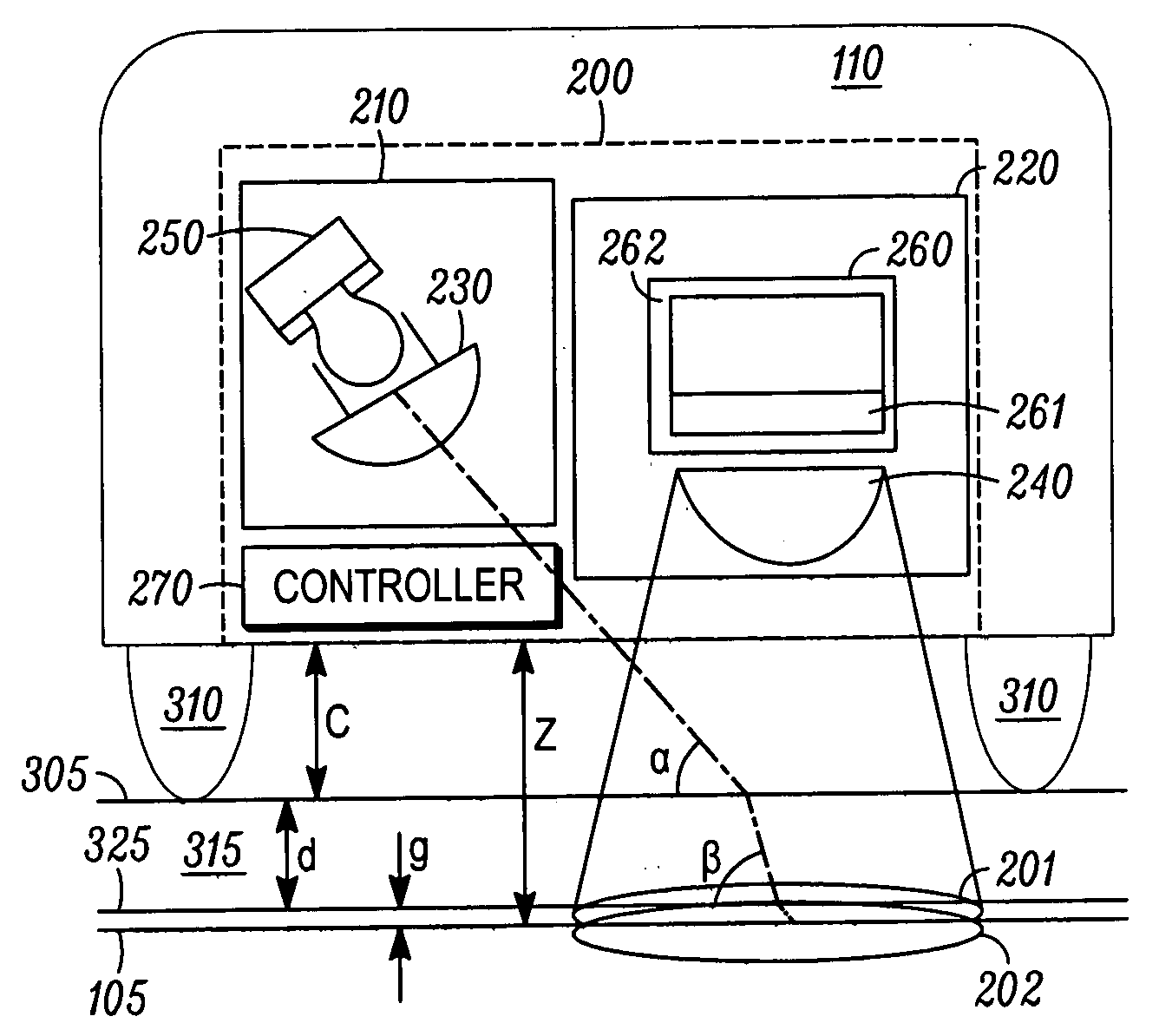
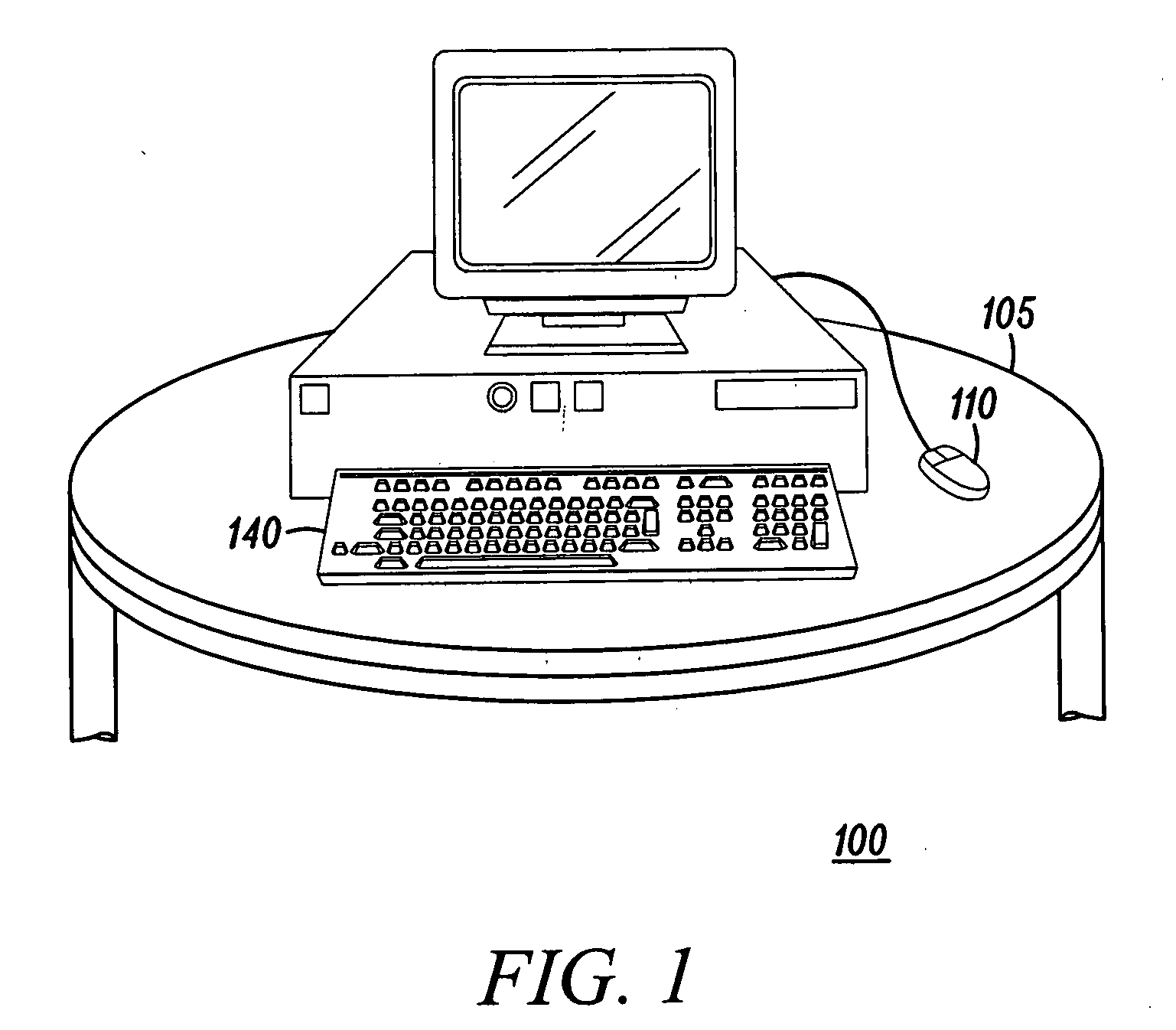
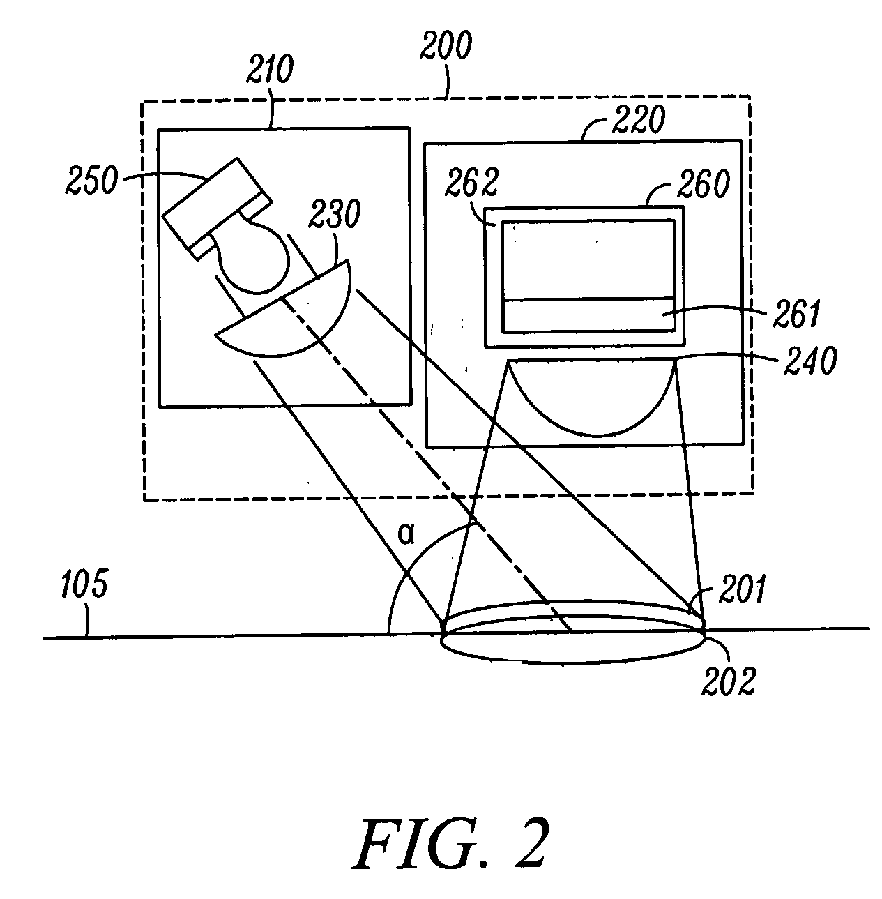
[0058] The figures (or drawings) depict a preferred embodiment of the present invention for purposes of illustration only. It is noted that similar or like reference numbers in the figures may indicate similar or like functionality. One of skill in the art will readily recognize from the following discussion that alternative embodiments of the structures and methods disclosed herein may be employed without departing from the principles of the invention(s) herein. It is to be noted that although the following description of the preferred embodiments of the present invention is presented in the context of an optical mouse, there are other optical devices that can use the present invention such as, for example, an optical scanner, an optical digital writing system (e.g., Logitech IO pen by Logitech, Inc. of Fremont, Calif.), or an optical printer advance mechanism. Also, it is to be noted that the words “transparent” is sometimes used as a shorthand for referring to “transparent and / or...


PUM


Abstract

Embodiments of the present invention enable an optical device to track on a diffusing surface over which a transparent and/or translucent and/or optically smooth surface is placed. Some embodiments are directed towards detecting when an optical device is lifted off the surface it was resting on. Embodiments also include a sensing system that detects the z distance (distance to the tracking surface) and improves image quality by improving the effectiveness of the optical sensor subsystem and/or the illumination subsystem at the detected z distance. Other embodiments include a system and method that enables an optical device to track on a transparent and/or translucent and/or optically smooth surface alone. This may involve dark-field imaging based on certain features (e.g., dirt) already present on the transparent surface. Alternately, this may involve creating features such as droplets, spreading dirt residue, and creating thermal spots, which can be used for tracking.

Description

CROSS-REFERENCES TO RELATED APPLICATIONS [0001] This application is related to co-pending provisional application No. 60 / 795,031, which is entitled “An Input Device for Tracking on Varied Surfaces” and which was filed on Apr. 26, 2006. This application is hereby incorporated herein in its entirety. [0002] This application is related to co-pending provisional application No. 60 / 749,996, which is entitled “Tracking on Varied Surfaces and Lift-Detection for an Input Device” and which was filed on Dec. 12, 2005. This application is hereby incorporated herein in its entirety. [0003] This application is related to co-pending provisional application No. 60 / 702,459, which is entitled “Optical Displacement Detection on Transparent or Translucent Surfaces” and which was filed on Jul. 25, 2005. This application is hereby incorporated herein in its entirety. [0004] This application is related to co-pending provisional application No. 60 / 696,023, which is entitled “Optical Displacement Detection...

Claims


Application Information

Patent Timeline
Patent Type & Authority Applications(United States)
IPC IPC(8): G09G5/08
CPCG06F3/03543G06F3/0317
Inventor THEYTAZ, OLIVIERSASSELLI, NICOLASKARAMATA, BORISCHAUVIN, NICOLAS
Owner LOGITECH EURO SA
Why Eureka
Try Eureka