
Method and apparatus for particulate removal and undesirable vapor scrubbing from a moving gas stream

a technology of moving gas stream and moving gas, which is applied in the direction of electrode cleaning, dispersed particle separation, separation process, etc., can solve the problems of insufficient collection of particulate matter, and low gas residence time of such conventional apparatuses. achieve the effect of high efficiency and compactness

Inactive Publication Date: 2007-01-11
EISENMANN CORP
View PDF52 Cites 18 Cited by
  • Summary
  • Abstract
  • Description
  • Claims
  • Application Information

AI Technical Summary

Benefits of technology

"The invention provides an apparatus and method for removing particulate matter and undesirable vapors from a gas stream simultaneously. The apparatus includes an ionizing electrode that charges the particulate matter and vapors, a scrubbing element that collects the charged particles, and a liquid applicator that adds a positive charge to a liquid film on the collecting surface. This attracts the charged particles to the liquid film. The technical effect is a highly efficient and compact apparatus for simultaneously removing particulate matter and vapors from a gas stream."

Problems solved by technology

The residence time for the gas within the charging section of such conventional apparatuses, however, is typically very low and, therefore such systems do not provide for substantial collection of particulate matter following charging.
Moreover, the collection and removal of negatively-charged particles from a gas stream in conventional systems and methods typically occurs in neutral scrubbers.
This limitation, in turn, typically calls for larger and more expensive equipment.

Method used


Image

  • Method and apparatus for particulate removal and undesirable vapor scrubbing from a moving gas stream
  • Method and apparatus for particulate removal and undesirable vapor scrubbing from a moving gas stream
  • Method and apparatus for particulate removal and undesirable vapor scrubbing from a moving gas stream

Examples


Embodiment Construction

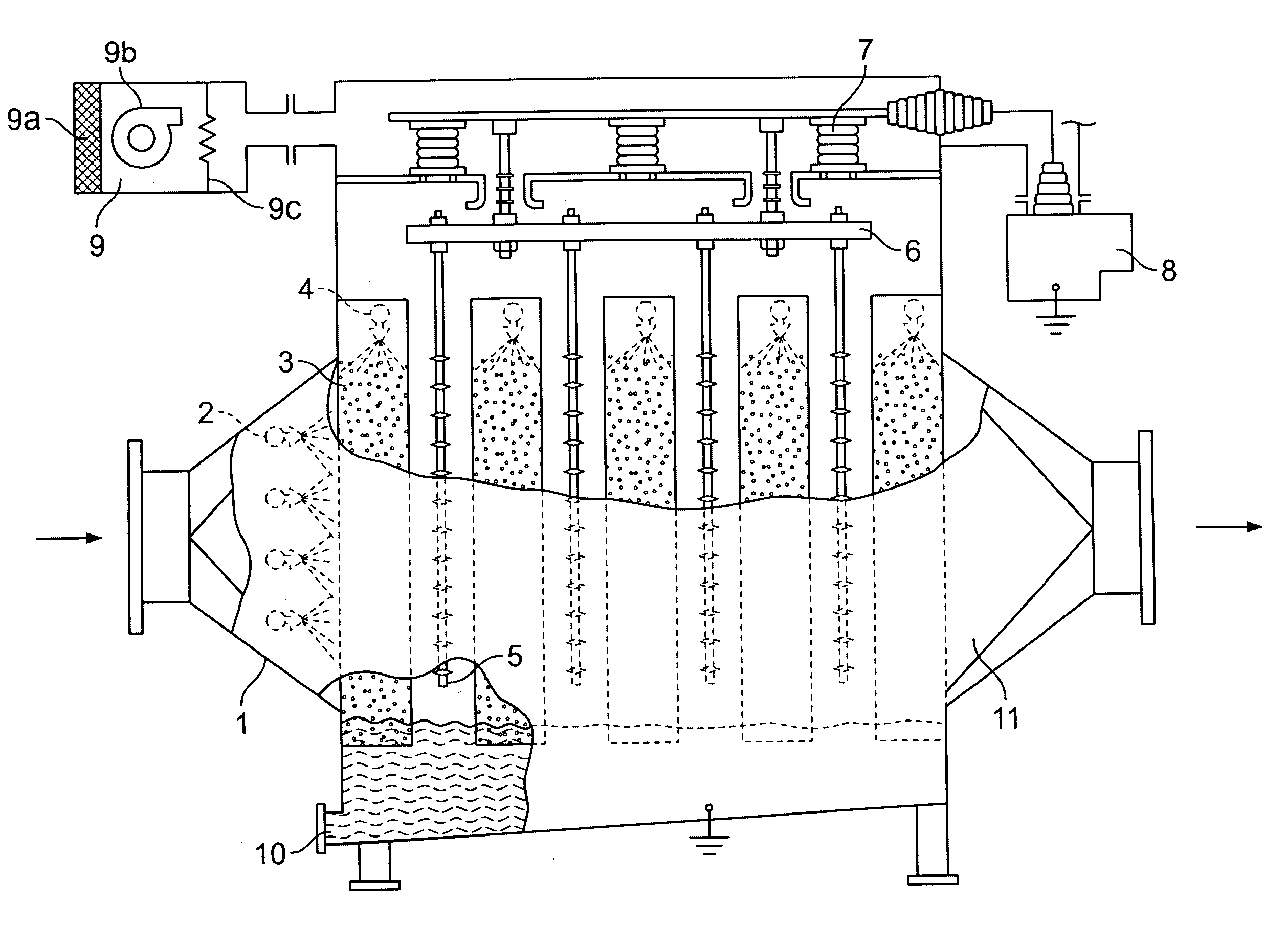
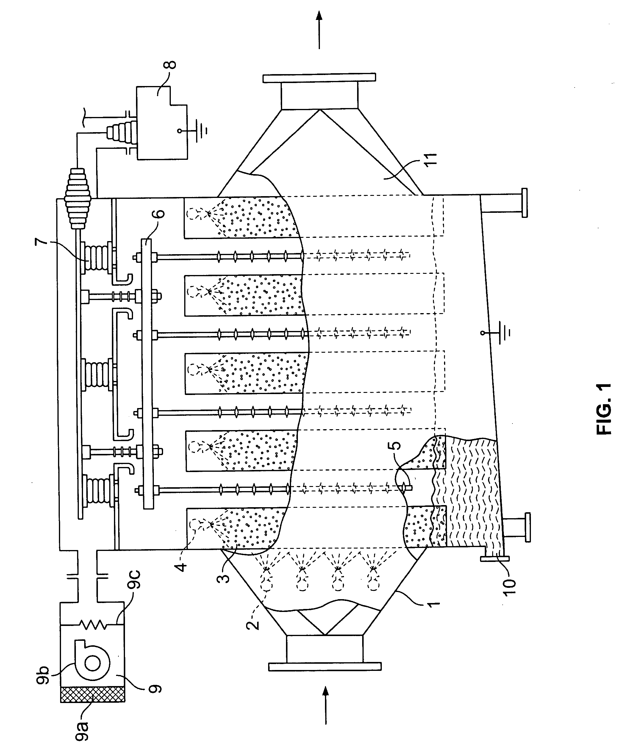
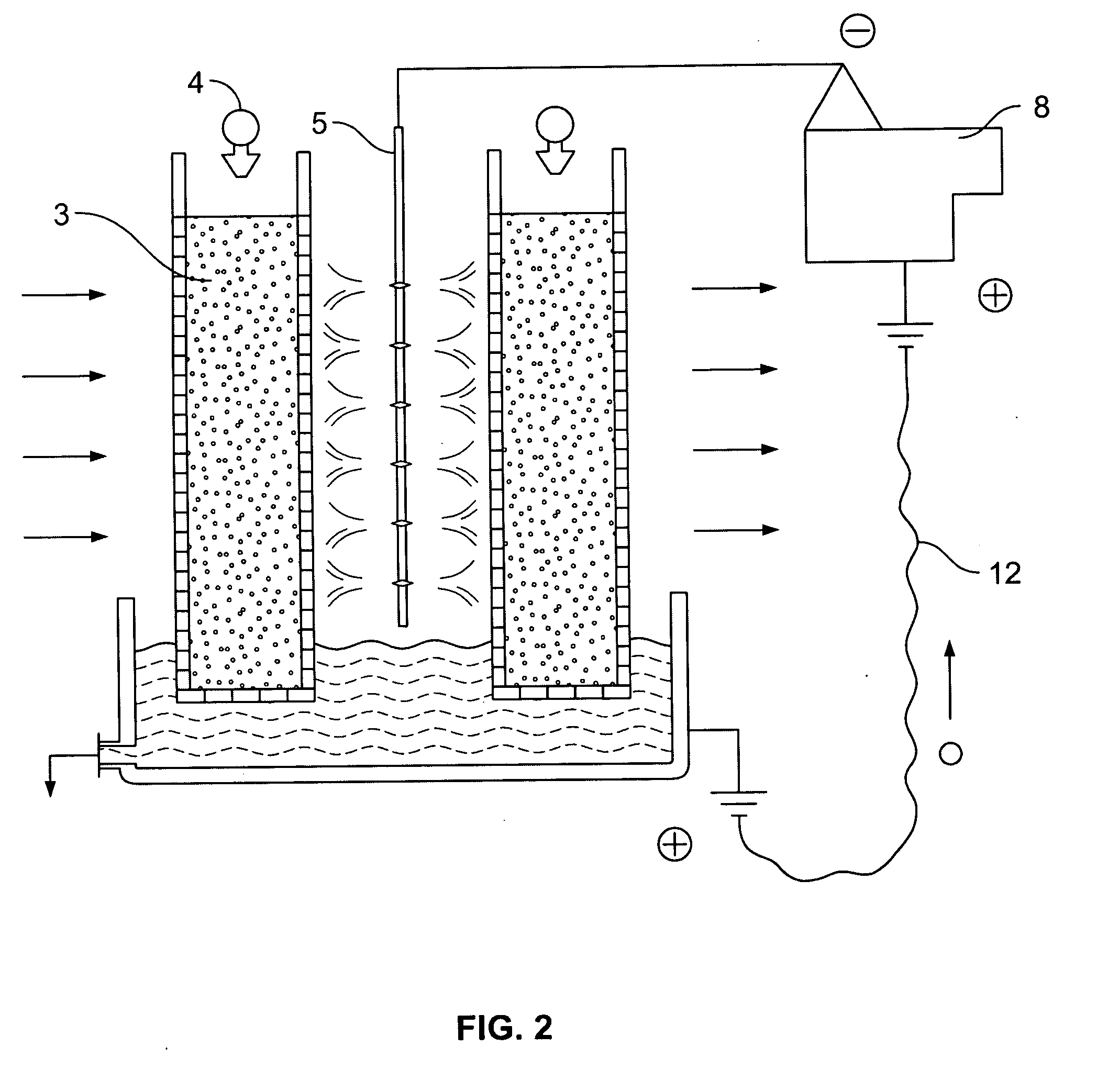
[0014] In one aspect, an apparatus is provided for removing particulate matter and undesirable vapors from a gas stream containing particulate matter and undesirable vapors. An example apparatus comprises at least one ionizing electrode that negatively charges the particulate matter and undesirable vapors, at least one scrubbing element including a collecting surface, and at least one liquid applicator operable to apply a liquid film to the collecting surface, wherein a positive charge is applied to the liquid film to attract negatively-charged particulate matter and / or undesirable vapors to the collecting surface.

[0015] In another aspect, a method is provided for removing particulate matter and undesirable vapors from a gas stream. An example method comprises the steps of: negatively charging the particulate matter and undesirable vapors using at least one ionizing electrode; applying a liquid film to a collecting surface proximate the ionizing electrode; and positively charging t...


PUM

PropertyMeasurementUnit
voltageaaaaaaaaaa
polarityaaaaaaaaaa
shapeaaaaaaaaaa

Abstract

An apparatus and method for removing particulate matter and undesirable vapors from a gas stream are provided. In one aspect, an apparatus includes at least one ionizing electrode that negatively charges the particulate matter and condensed droplets of undesirable vapors, at least one scrubbing element including a collecting surface, and at least one liquid applicator operable to apply a liquid film to the collecting surface, wherein a positive charge is applied to the liquid film to attract negatively-charged particulate matter and / or condensed droplets of undesirable vapors to the collecting surface. In another aspect, a method includes the steps of: negatively charging the particulate matter and condensed droplets of undesirable vapors using at least one ionizing electrode; applying a liquid film to a collecting surface proximate the ionizing electrode; and positively charging the liquid film to attract the negatively-charged particulate matter and condensed droplets of undesirable vapors.

Description

CROSS-REFERENCE TO RELATED PATENT APPLICATIONS [0001] This patent application claims the benefit of U.S. Provisional Patent Application No. 60 / 697,782, filed Jul. 8, 2005.FIELD OF THE INVENTION [0002] This invention pertains to a method and apparatus for particulate matter removal and for undesirable vapor scrubbing from a gas stream. BACKGROUND OF THE INVENTION [0003] There have been continuing attempts to improve techniques for removing fine particulates from gas streams. In conventional systems, contaminated gas streams are typically cleansed of particulate matter by charging the particular matter in a charging section of an apparatus. The residence time for the gas within the charging section of such conventional apparatuses, however, is typically very low and, therefore such systems do not provide for substantial collection of particulate matter following charging. Moreover, the collection and removal of negatively-charged particles from a gas stream in conventional systems and...

Claims


Application Information

Patent Timeline
Patent Type & Authority Applications(United States)
IPC IPC(8): B01D53/46
CPCB01D46/0035B01D46/10B01D53/78B01D53/323B01D46/50B03C3/16B03C3/41B03C3/53B03C3/64B03C3/78B03C3/86B03C2201/10
Inventor RAY, ISAACWEST, MARK A.ALTSHULER, BORIS
Owner EISENMANN CORP
Learn More