Explosive device utilizing flux compression generator

a technology of flux compression and explosive device, which is applied in the direction of white arms/cold weapons, protective equipment, weapons, etc., can solve the problems that conventional shaped charges and explosively formed penetrators (efp) cannot always cannot meet the requirements of multiple roles, and requires very large lengths and weights, so as to achieve greater efficiency in converting explosive energy

Active Publication Date: 2017-05-23
ENIG ASSOCS
View PDF3 Cites 6 Cited by
  • Summary
  • Abstract
  • Description
  • Claims
  • Application Information

AI Technical Summary

Benefits of technology

[0022]The present invention allows a compact, multiple kinetic energy, and/or high explosive, and/or blast effects to act on a target.
[0023]The presen

Problems solved by technology

Prior FCG state-of-art technology does not lend itself to weapons for multimodal roles.
Conventional shaped charges and Explosively Formed Penetrators (EFP) also cannot always meet requirements for multiple roles.
When a follow-through munition is utilized, the tandem and follow-through devices are placed in series, which demands very large lengths and high weights.
Often, length and weight constraints of the carrier system (projectiles or missiles) preclude the use of conventional approaches.

Method used


Image

  • Explosive device utilizing flux compression generator
  • Explosive device utilizing flux compression generator
  • Explosive device utilizing flux compression generator

Examples


Embodiment Construction

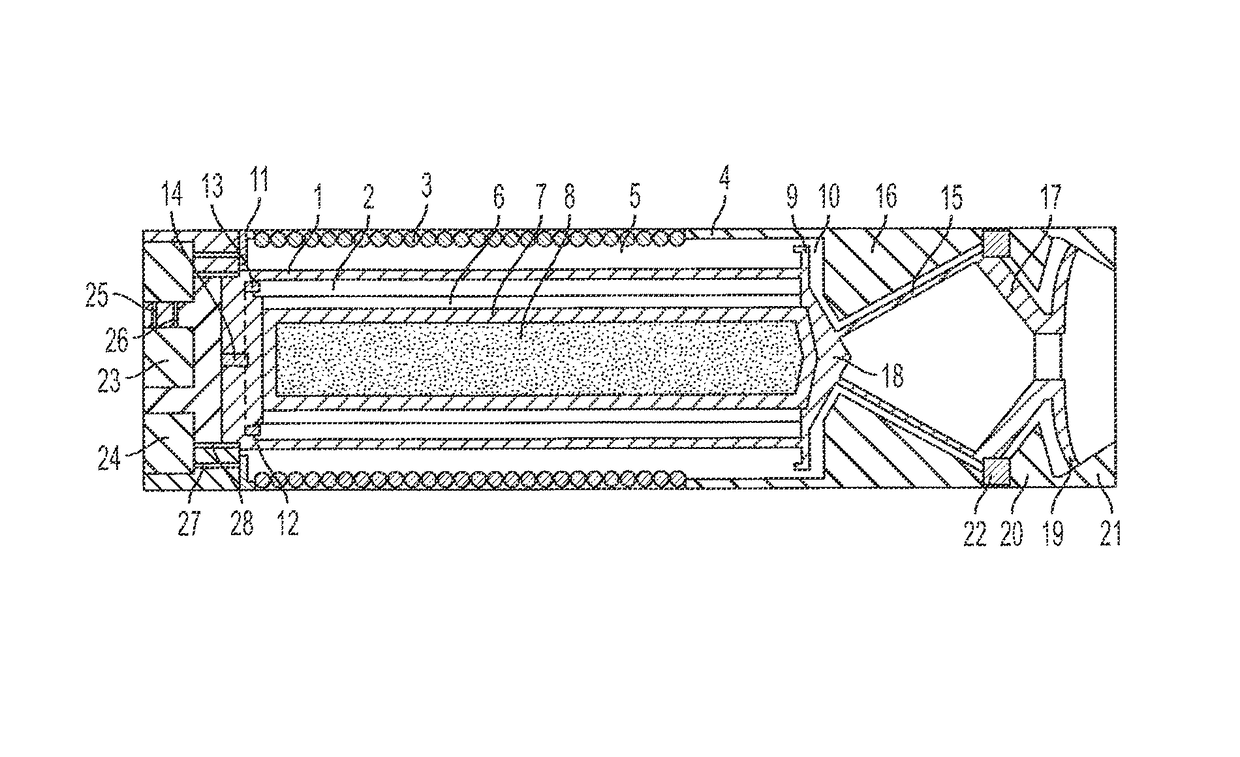
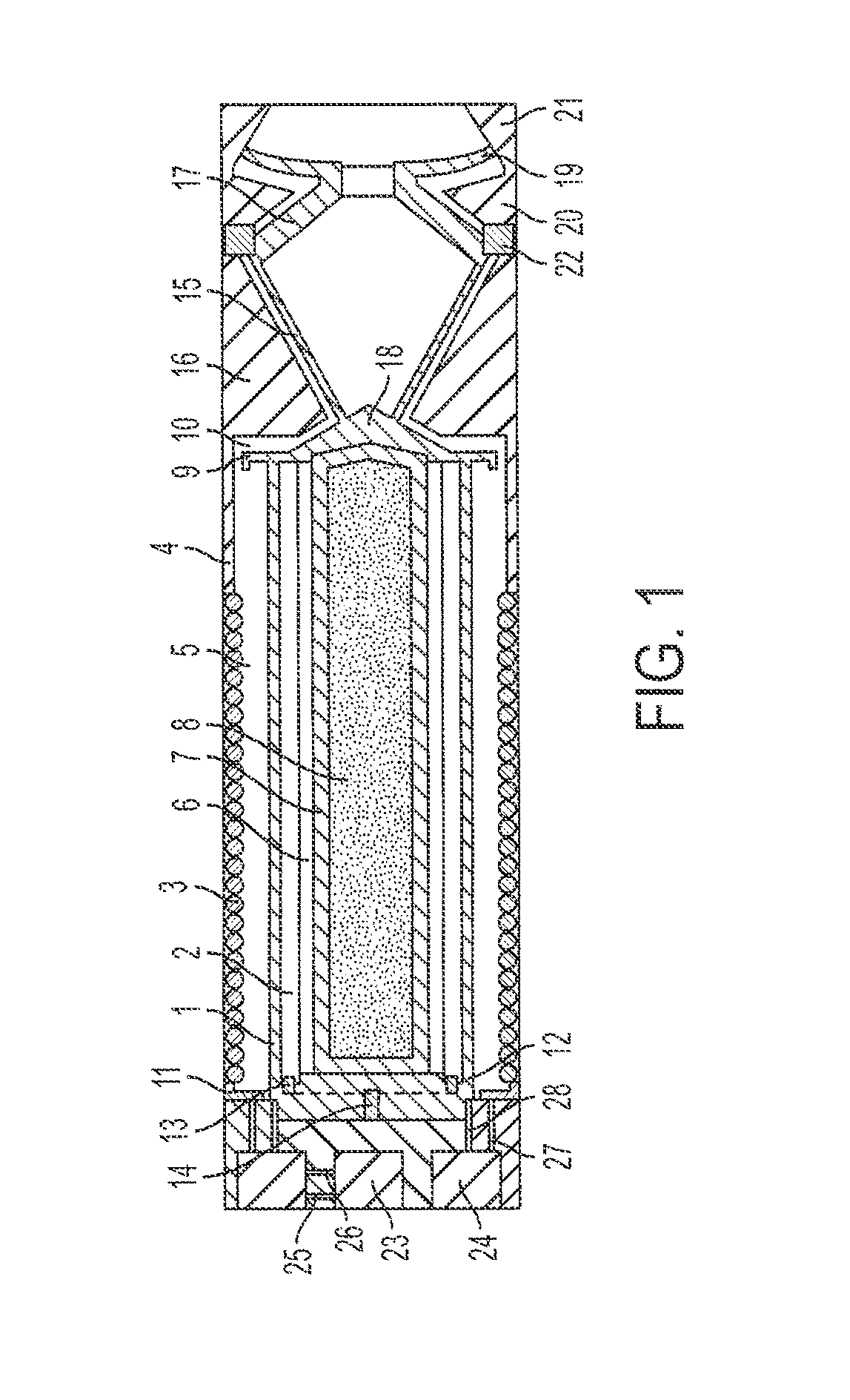
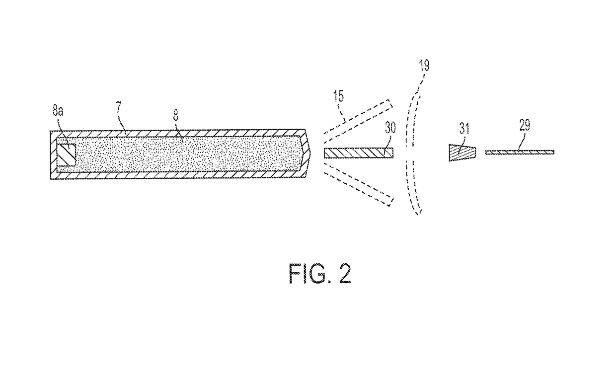
[0031]The basic components of an explosive device for launching kinetic energy according to the invention are shown in FIGS. 1 and 3. The device includes a flux compression generator, electrical loads composed of two shaped charge liners, a central munition, a means to detonate the high explosives, and an electronic unit to produce starting current for the generator.

[0032]As shown, the FCG portion of the system has an armature 1, an annular shell of high explosives (HE) 2 enclosed by armature 1, a helical wound stator 3 surrounding armature 1, a stator 4 aligned with, and electrically connected to, stator 3, and a cavity 5. A buffer 6 separates high explosives 2 from the centrally located munition having a metallic casing 7 that is filled with explosive 8 having its own detonator 8a. The generator output end, to the right in FIG. 1, contains an armature glide rail 9 and an insulated channel 10. The initiation end that is opposite to the output end utilizes glide rail 11 together wit...


PUM


Abstract

An explosive device composed of: a flux compression generator operative to produce a high intensity electric current when activated; and an electrical payload connected to the generator and constructed to receive the high intensity electric current and cause energy in the current to generate a shaped projectile in the payload and to launch the projectile.

Description

BACKGROUND OF THE INVENTION[0001]The present invention relates to projectiles containing a flux compression generator (FCG) for producing a high current that acts to produce a metal mass in a manner to project that mass as a jet to penetrate a target.[0002]Flux compression generators are already known in the art. An example thereof is disclosed in U.S. Pat. No. 4,370,576, Foster, Jr., issued on Jan. 25, 1983, and the entirety of which is incorporated herein by reference.[0003]It is known that extremely high magnetic fields can be obtained using high explosives as an energy source in devices known as flux compression generators. In such a generator, an explosive detonation compresses an established low-level magnetic field into a very high density field, with an associated high electrical current flow. Typically, a low-level magnetic field is established within a confined space or cavity and acted upon by the force of explosive detonation to collapse that space to a relatively small ...

Claims


Application Information

Patent Timeline
IPC IPC(8): F41H1/00F41B6/00
CPCF41B6/006
Inventor GRACE, FRED IRVINENIG, ERIC N.KIM, YIL BONG
Owner ENIG ASSOCS
Why Eureka
Try Eureka