Recoil reduction and sighting-in system for a firearm

a recoil reduction and sighting-in system technology, applied in the field of recoil reduction and sighting-in systems for firearms, can solve the problems of recoil injury risk, heavy sighting stand weight, and inconvenient use, and achieve the effect of reducing or virtually eliminating the risk of injury as a result of recoil and being highly compact and light-weigh

Inactive Publication Date: 2012-11-15
CAMA MARK R
View PDF13 Cites 7 Cited by
  • Summary
  • Abstract
  • Description
  • Claims
  • Application Information

AI Technical Summary

Benefits of technology

[0011]The system described herein solves the problems of the prior art by providing a recoil reduction strap that includes an attachment portion configured to attach to the shooting bench and a sling that goes about the buttstock of the firearm to absorb the recoil of the firearm when it is fired. The system may optionally further include a plate to provide a hard surface for a bipod to rest on. Because the strap absorbs the recoil from the firearm the firearm remains highly stable during the sighting-in process. Furthermore, the risk of injury as a result of recoil is significantly reduced or virtually eliminated. The system is also highly compact and light-weight making the system a significant improvement over prior art sighting stands.

Problems solved by technology

Every time the rifle is fired recoil from the cartridge exploding will necessarily move the rifle, which can cause hunter's pain and cause them to flinch in anticipation of the recoil.
If the hunter flinches it will introduce an error in the sighting in process.
However, these sighting stands are heavy and expensive.
Second, because the hunter is firing multiple sets of rounds during the sighting in process, the hunter may suffer an injury induced by the recoil of the firearm if the hunter is not properly prepared to absorb the recoil, is fatigued, is firing a high-power cartridge, the hunter is small or frail of stature, such as a child, elderly person, is inexperienced, or a combination of the above conditions exist.

Method used


Image

  • Recoil reduction and sighting-in system for a firearm
  • Recoil reduction and sighting-in system for a firearm
  • Recoil reduction and sighting-in system for a firearm

Examples


Embodiment Construction

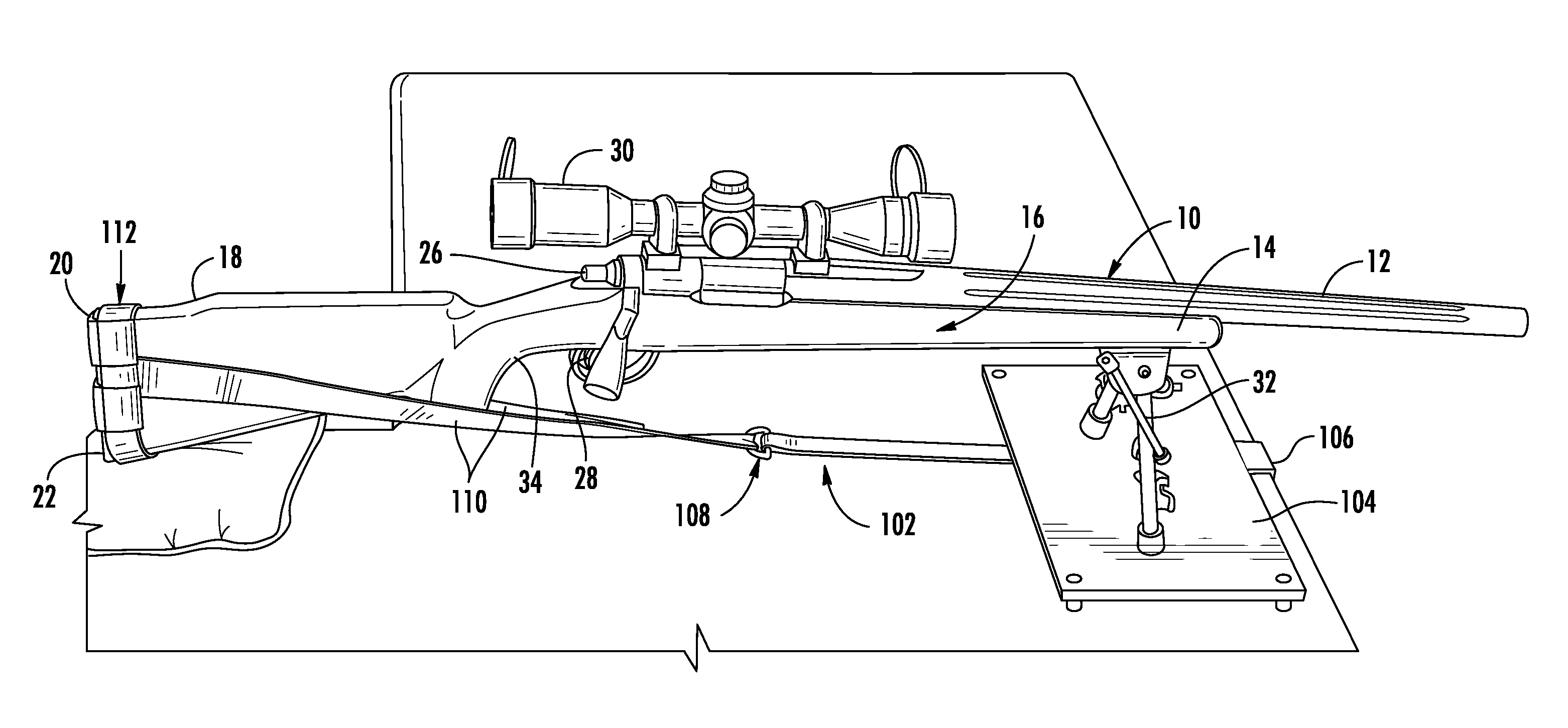
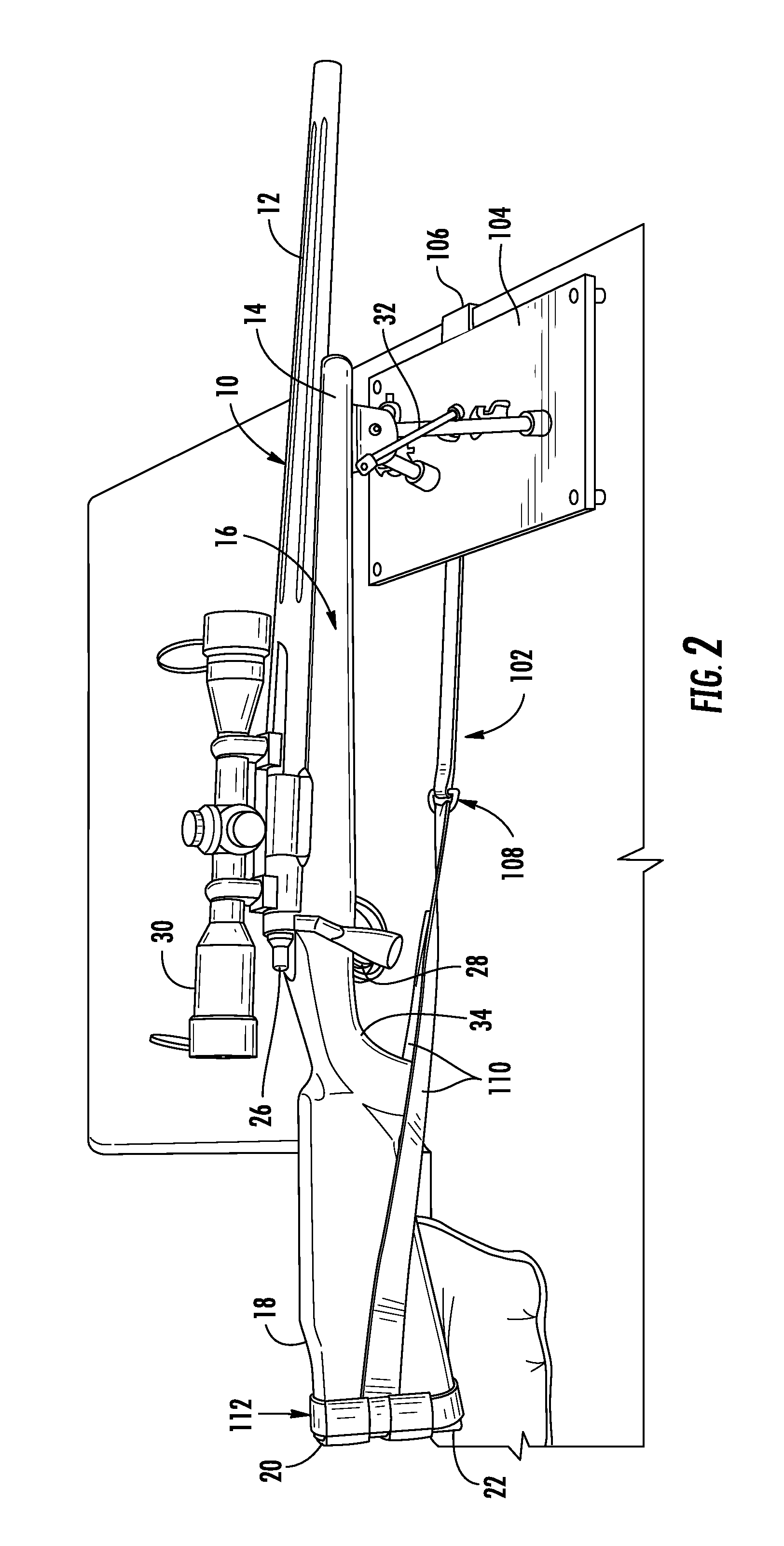
[0030]The recoil reduction and sighting-in system is shown generally at 100 in FIGS. 2 and 3 set up with a firearm 10, such as a bolt action rifle having a scope 30. The system 100 includes a strap 102 and an optional leveling stand 104 (best seen in FIG. 12).

[0031]Turning first to the strap 102, the strap 102 includes an attachment member 106 for attaching to the end of a shooting bench at a firing range. As shown in FIGS. 4A-C, the attachment member 106 may be formed as a single hook 106a (FIG. 4A), as multiple hooks or a claw 106b (FIG. 4B), or an adjustable clamp 106c (FIG. 4C). Other structures may be used to attach the end of the strap 102 to the shooting bench.

[0032]The strap 102 is preferably formed from a tough and durable material, such as nylon webbing, but other materials may be used.

[0033]About midway down the strap 102 is a strap adjuster 108, which may be formed in a number of different structures as shown in FIG. 5A-C, a buckle 108A (FIG. 5A), stamped metal strap adj...


PUM


Abstract

A recoil reduction system for sighting-in a firearm is disclosed. The system includes an attachment member configured and arranged to attach to a surface or object, such as a shooting bench, tree stand or a tree. A strap having a first end and a second end is included. The first end of the strap is connected to the attachment member. A sling is formed on the second end of the strap. The sling has a loop configured and arranged to receive the buttstock of a rifle. A stand having a rigid plate configured and arranged to support a bipod of a rifle may also be included.

Description

CROSS-REFERENCE TO RELATED APPLICATION[0001]This patent document claims priority to earlier filed U.S. Provisional Patent Application Ser. No. 61 / 485,231, filed on May 12, 2011, the entire contents of which are incorporated herein by reference.BACKGROUND[0002]1. Technical Field[0003]The present patent document relates generally to firearms accessories and more specifically to an apparatus and method to reduce recoil while sighting-in a scope on a firearm.[0004]2. Background of the Related Art[0005]Sighting-in a telescopic sight (or “scope”) for a firearm is a process, some might call a ritual, for hunters to align and calibrate the scope so that the crosshairs of the scope converge with the barrel over predetermined distances for specific types of ammunition.[0006]Referring to FIG. 1, an exemplary firearm 10 is shown generally. The firearm 10 shown is a bolt-action rifle, which generally includes barrel 12, a forend 14 of the stock 16 supporting the barrel and functions as a forward...

Claims


Application Information

Patent Timeline
Patent Type & Authority Applications(United States)
IPC IPC(8): F41C27/00
CPCF41A23/16
Inventor CAMA, MARK R.
Owner CAMA MARK R
Why Eureka
Try Eureka