Liquid receiver combined with liquid separator for refrigeration cycle and manufacturing method thereof

A gas-liquid separator, refrigeration cycle technology, applied in refrigeration and liquefaction, compressors with reversible cycle, refrigerators, etc., can solve problems such as failure of smooth compressor damage, poor separation, etc. The effect of reducing defect rate and cost

Inactive Publication Date: 2012-11-28
陈玪洙
View PDF6 Cites 5 Cited by
  • Summary
  • Abstract
  • Description
  • Claims
  • Application Information

AI Technical Summary

Problems solved by technology

[0004] However, in the refrigerating cycle, the flow rate of the refrigerant is appropriately adjusted by the expansion valve. If the refrigerant amount equivalent to evaporation in the evaporator is supplied to the evaporator, the state of the refrigerant after evaporation will be a dry saturated state, but the flow rate regulated by the expansion valve When the amount of refrigerant evaporated in the evaporator is greater than the optimum amount of refrigerant or the cooling load is reduced, the evaporation efficiency is reduced, the separation of refrigerant vapor and refrigerant liquid is poor, and it is sucked into the compressor, so there is a problem of preventing compressor damage. function problem

Method used


Image

  • Liquid receiver combined with liquid separator for refrigeration cycle and manufacturing method thereof
  • Liquid receiver combined with liquid separator for refrigeration cycle and manufacturing method thereof
  • Liquid receiver combined with liquid separator for refrigeration cycle and manufacturing method thereof

Examples


Embodiment Construction

[0022] Hereinafter, preferred embodiments of the present invention will be described in detail with reference to the accompanying drawings.

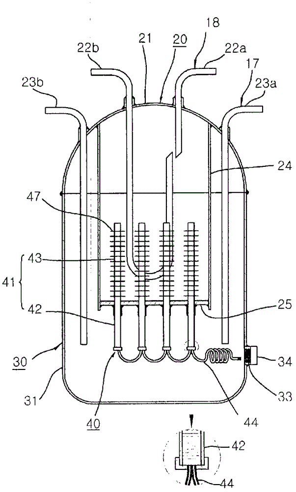
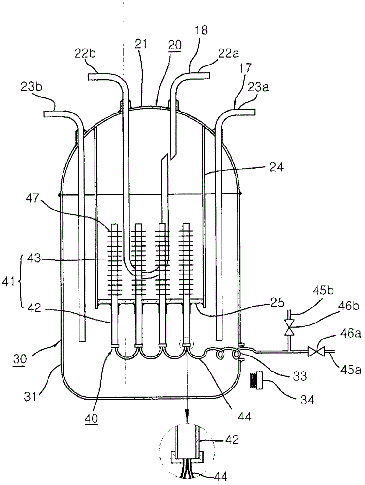
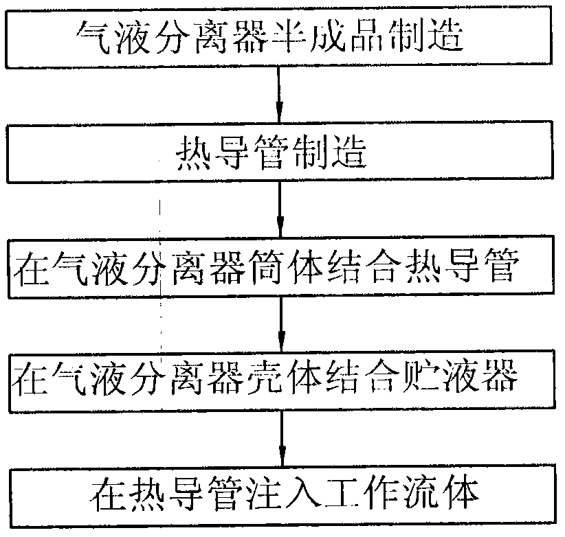
[0023] figure 1 is a cross-sectional view of an embodiment of the present invention, figure 2 is a state diagram before the heat pipe injects the working fluid in the embodiment of the present invention, image 3 is a manufacturing engineering drawing of an embodiment of the present invention, Figure 4 It is an installation example diagram of an embodiment of the present invention, that is, the structure of the present invention is roughly divided into a gas-liquid separator 20 , a liquid reservoir 30 and a heat pipe 40 .

[0024] The gas-liquid separator 20 is composed of a vertical refrigerant vapor inflow conduit 22a and a hook-shaped refrigerant vapor discharge conduit 22b formed at the opposite part after the arc-shaped shell 21 is welded and connected to cut off the suction conduit 18 halfway. ; The refrigerant vapor inflow co...


PUM


Abstract

The present invention relates to a liquid receiver combined with a liquid separator for a refrigeration cycle and a manufacturing method thereof; and more particularly, to a liquid receiver combined with a liquid separator for a vapor-compression refrigeration cycle and a manufacturing method thereof, by which manpower and working hours are reduced and the defect rate is reduced, thereby improving the productivity. The present invention comprises: a liquid separator (20), which includes a cover (21) with a cut portion of a refrigerant vapor suction conduit (18) and a cut portion of a refrigerant conduit (17) connected at the inside and outside thereof, respectively, facing each other, a cylindrical body (24) with the upper end coupled to the cover (21) in such a manner to surround the refrigerant vapor suction conduit (18), and a base plate (25) formed at the lower end of the cylindrical body (24); a liquid receiver (30), which has a main body (31) with the upper end being coupled to both ends of the cover, and a side wall (32) with an outlet opening (33) formed therein; ; and a heat pipe (40), which includes a plurality of main bodies (41) weld-bonded to the base plate (25) of the liquid separator, an evaporator (42) weld-bonded to the inside of the main body (31) of the liquid receiver, a condenser (43) weld-bonded to the inside of the liquid separator (20), and an exhaust pipe combined with a working fluid injection pipe (44) connected to the lower end of the main body (41) of each heat pipe in such a way to allow the heat pipe main bodies (41) to get interconnected in a communicating manner, whereby after a working fluid is injected to the heat pipe main bodies (41) an entrance of the exhaust pipe combined with the working fluid injection pipe (44) is cut and closed and the closure is then pushed inside the outlet opening (33).

Description

technical field [0001] The invention relates to a liquid receiver and gas-liquid separator for a refrigeration cycle and a manufacturing method thereof, in particular to a liquid receiver and a gas-liquid separator for a vapor compression refrigeration cycle and a manufacturing method thereof. Background technique [0002] As we all know, the refrigeration cycle performed by the refrigerator and the heat pipe is to use the refrigerant pipe to connect the compressor, the four-way valve, the indoor heat exchanger, the expansion valve, the outdoor heat exchanger and the four-way valve in sequence, and the refrigerant The steam suction conduit connects the four-way valve and the compressor. When the refrigerator is running, after the outdoor heat exchanger condenses the high-temperature and high-pressure refrigerant vapor compressed by the compressor, the indoor heat exchanger evaporates the refrigerant liquid. After the heat of evaporation is refrigerated, the low-temperature, ...

Claims


Application Information

Patent Timeline
Patent Type & Authority Applications(China)
IPC IPC(8): F25B43/02F25B43/00
CPCF25B2400/23F25B13/00F25B43/006F25B2500/18F25B2400/16Y10T29/49396F25B43/00F25B43/02
Inventor 陈玪洙
Owner 陈玪洙
Why Eureka
Try Eureka